Illumination, Signals and ITS - IS
Details and guidance for fabrication and installation of signals, illumination and ITS.
Index of Details
Use the following index links to go directly to that detail:
- IS-1: Pedestrian Pushbutton Post (PPB) and Foundation
- IS-2: Accessible Pedestrian Signal (APS) Pushbutton Extension
- IS-9: Conduit Deflection Fitting Sleeve Detail
- IS-10: Cabinet Shipping Pallet
- IS-12: Accessible Pedestrian Signal (APS) Pushbutton Post Placement
- IS-13: Signal Standard Charts for Traffic Signals, Ramp Meters, and Rapid Flashing Beacon Systems
- IS-15: Signal Bridge Standard Details
- IS-16: High-Mast Luminaires
- IS-17: Pole Hole Repair Procedure
- IS-18: Vault Drainage Installation Details
- IS-19: P44 Cabinet Riser Adaptor Base
- IS-20: 332 Cabinet Riser Adaptor Base
- IS-22 and IS-23: Rapid Flashing Beacon (RFB) Details and Pedestrian Crossing Details
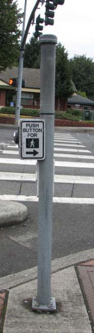
Pedestrian Pushbutton (PPB) Post and Foundation
(IS-1)
This plan provides the necessary details for installing a pedestrian push button post with one or two H-frame type pushbuttons.
Note: IS-1 is provided for modification of existing H-frame type pushbuttons where allowed, including placement of a new Type PPB signal standard. See the Standard Plans for APS pushbutton installation information, and Detail IS-2 for APS pushbutton extensions.
Image
View the Pedestrian Push Button Post and Foundation plan sheet (PDF 290KB)
Accessible Pedestrian Signal (APS) Pushbutton Extension
(IS-2)
This plan provides the necessary details for installing an APS PPB extension.
Image
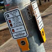
An APS PPB extension is only used where APS PPB cannot be made accessible by other means. Generally, this will be on existing traffic signal systems where foundations limit the ability to bring sidewalk closer to the APS PPB or locations where the APS needs to be extended over guardrail. New construction should be designed to avoid the need for APS PPB extensions.
View the Accessible Pedestrian Signal (APS) Pedestrian Pushbutton (PPB) Extension plan sheet (PDF 118KB)
Download the Accessible Pedestrian Signal (APS) Pedestrian Pushbutton (PPB) Extension WinZip file (ZIP 368KB)
(WinZip file contains the following file formats: .dgn, .dwg, and .doc files)
Conduit Deflection Fitting Sleeve Detail
(IS-9)
This drawing shows the necessary details for placing Conduit Sleeves around the Conduit Deflection Joints installed in Retaining Wall Traffic Barriers.
Image
Conduit Deflection Joint with Sleeve
Image
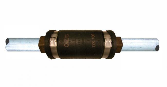
Exposed Conduit Deflection Fitting
This drawing is intended to supplement Standard Plans J-60.11 and J-60.12, Bridge Traffic Barrier plans, and retaining wall plans that require a conduit deflection joint. It should be included as a detail in any contract with these features.
Conduit Deflection Joints protect the conduit and wires where they pass through the barrier/retaining wall expansion joint that is coincident with the footing construction joint. Use of Conduit Deflection Fittings at these junctures diminishes the threats posed by structural movement and the weather.
The sleeve is applied to accommodate the differential movement of the concrete during the pour, and to maximize protection of the fitting during construction. It consists of a casing of polystyrene foam wrapped in duct tape. The foam has a relatively high friction resistant surface that provides sufficient durability. This is enhanced by the tape which is intended to weatherproof the sleeve while exposed, and to resist concrete intrusion during the pour.
View the Conduit Sleeve Detail plan sheet (PDF 148KB)
Download the Conduit Sleeve Detail WinZip file (ZIP 134KB)
(WinZip file contains the following file formats: .dgn, .dwg, and .doc files)
Cabinet Shipping Pallet
(IS-10)
This plan depicts the minimum dimensional requirements for an approved shipping pallet for use transporting electrical equipment for projects.
Image

Securing the cabinet to the pallet will provide a safe and easily maneuverable load when proper equipment is used for handling. Accidental tipping of the unit is greatly decreased when the cabinet is secured to the pallet.
View the Cabinet Shipping Pallet plan sheet (PDF 43KB)
Download the Cabinet Shipping Pallet WinZip file (ZIP 66KB)
(WinZip file contains the following file formats: .dgn, .dwg, and .doc files)
Accessible Pedestrian Signal (APS) Pushbutton Post Placement
(IS-12)
This drawing is intended to support the following Standard Plans:
- Accessible Pedestrian Pushbutton Post (PPB) and Foundation (J-20.10)
- Accessible Pedestrian Pushbutton (PPB) with Curb Base (J-20.11)
- Accessible Breakaway Pedestrian Pushbutton (PPB) Post (J-20.15)
- Pedestrian Signal Standard (Type PS) Details (J-20.16)
- Accessible Pedestrian Pushbutton (PPB) Details (J-20.26)
The drawings use the ADA (American Disabilities Act) guidelines as outlined in the MUTCD.
View the Accessible Pedestrian Pushbutton Post Placement plan sheet (PDF 46KB)
Download the Accessible Pedestrian Pushbutton Post Placement WinZip file (ZIP 191KB)
(WinZip file contains the following file formats: .dgn, .dwg, and .doc files)
Signal Standard Charts for Traffic Signals, Ramp Meters, and Rapid Flashing Beacon Systems
(IS-13)
Note: Include the following plan sheet(s) (as applicable) as part of the Contract Plans for any WSDOT Contract requiring the installation of any of the following Signal Standard Types:
- PPB
- PS
- RM
- FB
- I
- II
- III
Conventional Signal Standard Detail Chart (IS-13)
This plan provides the necessary details for installing conventional Signal Standards (Type PPB, PS, I, II, and III).
View Conventional Signal Standard Detail Chart plan sheet (PDF 270KB)
Type II or III Signal Standards with double arms at angles other than 90 degrees require design support from the Bridge and Structures Office.
For arms with five or more signal displays, an extended version of IS-13 (IS-13X) is available to assist in placement of additional signal displays or signs, and how to expand the attachment point columns if additional positions need to be added or modified.
View Extended Conventional Signal Standard Detail Chart plan sheet (PDF 274KB)
Ramp Meter Signal Standard Detail Chart (IS-13A)
This plan provides the necessary details for installing Signal Standards used in Ramp Meter Systems (Type RM, FB, and II).
View Ramp Meter Signal Standard Detail Chart plan sheet (PDF 257KB)
Rapid Flashing Beacon (RFB) System Standard Detail Chart (IS-13B)
This plan provides the necessary details for installing Signal Standards used in RFB Systems (Type FB and II).
View Rapid Flashing Beacon (RFB) System Standard Detail Chart plan sheet (PDF 340KB)
Foundation Design
Per the "Soil Investigation in the Signal Design Process" memorandum, Region electrical design groups need to contact the Region Materials Engineer (RME) and request soil condition data and foundation recommendations. The RME will assess the site's soils and topography for the proposed Signal Standard location. View Foundation Design Memorandum (PDF 88KB).
Based on the RME's assessment, there are two options:
1. If the soil conditions and slopes are such that a standard foundation design can be used, the RME will recommend to the Region electrical design group that the foundation depth be designed using the criteria contained within the applicable Standard Plan. Foundation depths shall be obtained from Standard Plan J-26.10 using the criteria contained therein.
View Standard Plan J-26.10 (PDF 64KB)
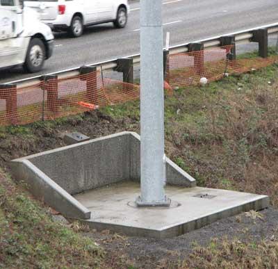
Standard Plan J-26.10 Foundation Construction Methods:
Image
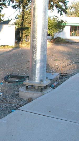
Alternate 1
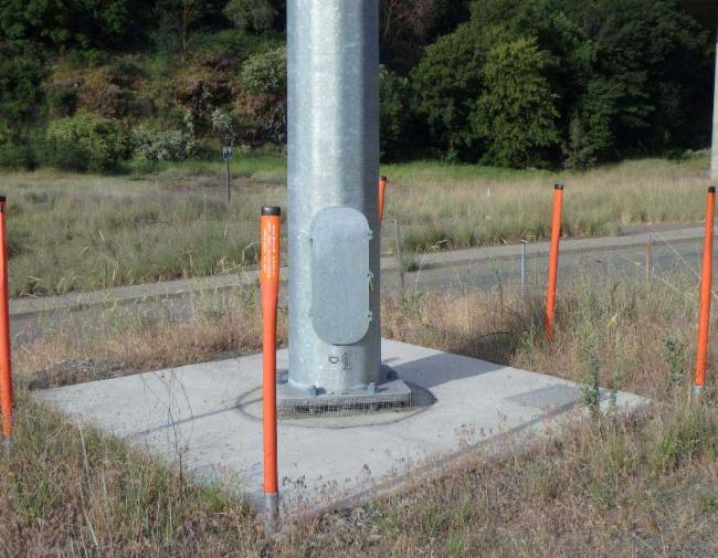
Image
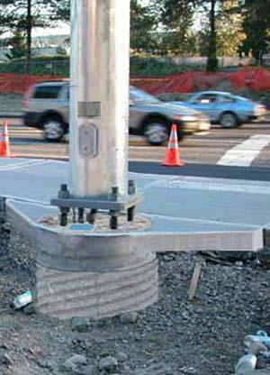
Alternate 2 (backfill material not shown)
2. If soil conditions or slopes will not allow for the use of a standard foundation design (such as soils that are too soft, loose or solid rock is encountered, or the slopes are too steep), the RME will recommend using a special foundation design. At this point, the RME may elect to provide the foundation design recommendations directly to the Bridge and Structures Office or request that the HQ Geotechnical Division provide the recommendations to the Bridge and Structures Office. In either case, the Bridge and Structures Office will be responsible for the development of the special foundation design.
In no case should an individual from the Region electrical design group select a standard foundation for use without the recommendation and concurrence of the RME.
Per the above memorandum, Region electrical design groups are directed to request a soils analysis, in memorandum format, from the RME. Please note the highlights, representing the specific information to be included for each project, in the provided template. View Soils Analysis Request Memo (PDF 27KB)
Plan Sheet IS-13
View IS-13 plan sheet (PDF 270KB)
Download the IS-13 WinZip File (ZIP 4.9MB)
(WinZip file contains the following file formats: .dgn and .dwg files)
Plan Sheet IS-13X
View IS-13X plan sheet (PDF 274KB)
Download the IS-13X WinZip File (ZIP 5MB)
(WinZip file contains the following file formats: .dgn and .dwg files)
Plan Sheet IS-13A
View IS-13A plan sheet (PDF 257KB)
Download the IS-13A WinZip File (ZIP 4.9MB)
(WinZip file contains the following file formats: .dgn and .dwg files)
Plan Sheet IS-13B
View IS-13B plan sheet (PDF 340KB)
Download the IS-13B WinZip File (ZIP 1.1MB)
(WinZip file contains the following file formats: .dgn and .dwg files)
Signal Bridge Standard Details
(IS-15)
Note: Include this plan sheet as part of the Contract Plans for any WSDOT Contract requiring the installation of a Signal Bridge Standard.
Signal Bridge Design
This plan provides the necessary details to install a Signal Bridge.
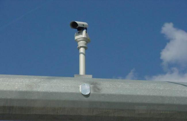
Image
Camera and associated hand hole on signal bridge
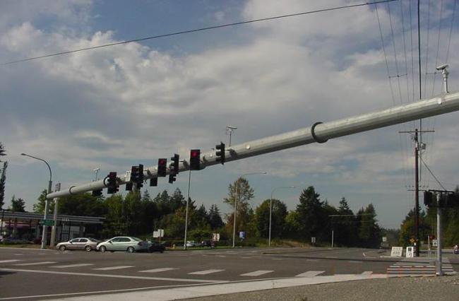
Image
Signal Bridge
Foundation Design
Per the "Soil Investigation in the Signal Design Process" memorandum, region electrical design groups need to contact the Region Materials Engineer (RME) and request foundation recommendations. The RME will assess the site's soils and topography for the proposed Signal Bridge Standard location. View the Foundation Design Memorandum (PDF 88KB).
The RME may elect to provide the foundation design recommendations directly to the Bridge and Structures Office or request that the HQ Geotechnical Office provide the recommendations. In either case, the Bridge and Structures Office or the Engineer of Record will be responsible for the development of the special foundation design.
In no case should an individual from a region electrical design group select a standard foundation for use without the recommendation and concurrence of the RME.
Per the above memorandum, region electrical design groups are directed to request a soils analysis, in memorandum format, from the RME. Please note the highlights, which represent the specific information to be included for each project, in the provided template. View Soils Analysis Request Memo (PDF 30KB)
View Signal Bridge Standard Details plan sheet (PDF 85KB)
Download the Signal Bridge Standard Details WinZip file (ZIP 90KB)
(WinZip file contains the following file formats: .dgn, .dwg, and .doc files)
High Mast Luminaires
(IS-16)
Note: Include this schedule detail as part of the Contract Plans for any WSDOT Contract requiring the installation of a High Mast Luminaire.
Designers: Reference- Include (IS-16a) High Mast Luminaire Maintenance Pad in the contract plans.
View High Mast Luminaires plan sheet (PDF 17KB)
Download the High Mast Luminaires WinZip file (ZIP 90KB)
(WinZip file contains the following file formats: .dgn, .dwg, and .doc files)
The design of a project lighting system using High Mast Luminaires requires a collaborative effort to determine; where to place the luminaires, the site specific conditions, and the structural analysis needed to provide an adequate foundation for the luminaires. The designer will capture the project design criteria in the schedule for use on the project and for ease of use by future designers.
This Luminaire Schedule is to be included in the development of any Contract Plan that requires the installation of a High Mast Luminaire.
View Luminaire Schedule plan sheet (PDF 17KB)
Download the Luminaire Schedule WinZip file (ZIP 90KB)
(WinZip file contains the following file formats: .dgn, .dwg, and .doc files)
Image
High Mast Luminaire Maintenance Pad on slopes level to 10H : 1V
Image
High Mast Luminaire Maintenance Pad on slopes steeper than 10H : 1V
Foundation Design
Per the "Soil Investigation in the Signal Design Process" memorandum, region electrical design groups need to contact the Region Materials Engineer (RME) and request foundation recommendations. The RME will assess the site's soils and topography for the proposed High Mast Luminaire location. View the foundation design memorandum (PDF 88KB).
The RME may elect to provide the foundation design recommendations directly to the Bridge and Structures Office or request that the HQ Geotechnical Office provide the recommendations. In either case, the Bridge and Structures Office or the Engineer of Record will be responsible for the development of the special foundation design.
In no case should an individual from a region electrical design group select a standard foundation for use without the recommendation and concurrence of the RME.
Per the above memorandum, region electrical design groups are directed to request a soils analysis, in memorandum format, from the RME. Please note the highlights, which represent the specific information to be included for each project, in the provided template. View Soils Analysis Request Memo (PDF 51KB)
Pole Hole Repair Procedure
(IS-17)
This plan describes how to repair an existing hole in a traffic standard. There are different methods of repair and they are dependent upon on the size of the existing hole to be repaired.
Image
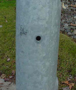
Existing hole
Image
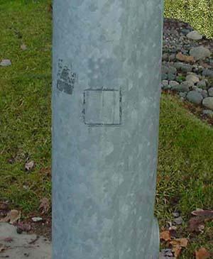
Patched hole
A welded patch example is shown here. See Plan Sheet for appropriate repair procedure.
View Traffic Standard Hole Repair Procedure plan sheet (PDF 45KB)
Download the Traffic Standard Hole Repair Procedure WinZip file (ZIP 788KB)
(WinZip file contains the following file formats: .dgn, .dwg, and .doc files)
Vault Drainage Installation Details
(IS-18)
Note: Include these details in the Contract Plans for any WSDOT Contract requiring drainage installation for Cable Vault, Pull Box or Small Cable Vault.
Drain Pipe Installation
This plan provides the necessary details to install drainage for Small Cable Vault, Pull Box or Cable Vault.\
Image
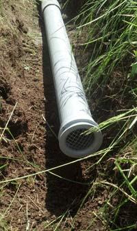
Excavated trench (backfill not shown here)
Image
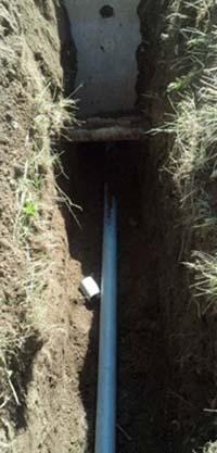
Drain pipe (backfill not shown here)
Image

Outfall
Image
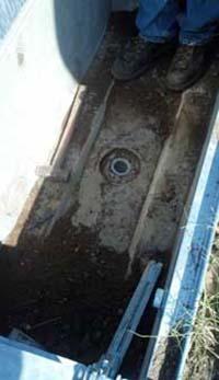
Existing sump drain
The Sump Drain Installation is intended for new installation or when slope is adequate for drainpipe to reach daylight. (Preferred method)
The Side Entrance Retrofit is intended to retrofit an existing Vault or Pull Box when minimum of 2% slope for drainpipe to reach daylight cannot be achieved.
View Cable Vault, Pull Box and Small Cable Vault Drainage Installation Details plan sheet (PDF 104KB)
Download the Cable Vault, Pull Box and Small Cable Vault Drainage Installation Details WinZip file (ZIP 90KB)
(WinZip file contains the following file formats: .dgn, .dwg, and .doc files)
P44 Cabinet Riser Adaptor Base
(IS-19)
These drawings detail the fabrication requirements for Controller Cabinet Riser Adaptor Bases. When Controller Cabinets require additional storage space for conductors, include these details in the Contract Plans.
Image
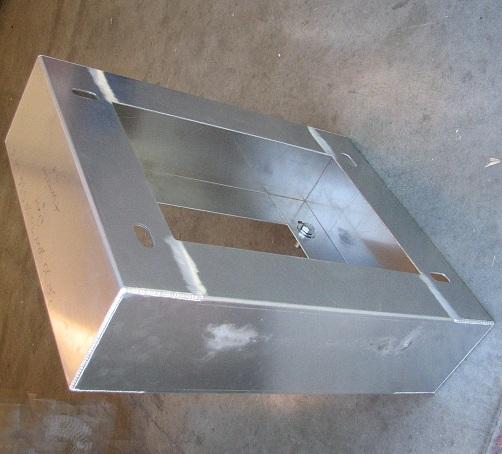
The P44 Riser Adaptor Base is intended to be used for new installation applications.
The P44 Riser Adaptor Split Base is intended to be used for retrofit applications.
The Region Electrical Design Group is responsible for specifying the installation locations.
View P44 Riser Adaptor Base plan sheet (PDF 61KB)
Download the P44 Riser Adaptor Base WinZip File (ZIP 352KB)
(WinZip File contains the following file formats: .dgn, .dwg files)
332 Cabinet Riser Adaptor Base
(IS-20)
These drawings detail the fabrication requirements for Controller Cabinet Riser Adaptor Bases. When Controller Cabinets require additional storage space for conductors, include these details in the Contract Plans.
Image

The 332 Riser Adaptor Base is intended to be used for new installation applications.
The 332 Riser Adaptor Split Base is intended to be used for retrofit applications.
The Region Electrical Design Group is responsible for specifying the installation locations.
View 332 Riser Adaptor Base plan sheet (PDF 61KB)
Download the 332 Riser Adaptor Base WinZip File (ZIP 350KB)
(WinZip File contains the following file formats: .dgn, .dwg files)
Rapid Flashing Beacon (RFB) Details & Pedestrian Crossing Details
(IS-22 & IS-23)
Note: Include the appropriate details from this page as part of the Contract Plans when an RFB system is included in a Contract.
These plans provide placement guidance and construction details for RFB system equipment. Details show both Rectangular Rapid Flashing Beacon (RRFB) and Circular Rapid Flashing Beacon (CRFB) configurations.
Guidance
Guidance for the installation of these types of crossings is described in Chapter 4 of the WSDOT Traffic Manual. Typical equipment layouts and placements are shown in detail IS-23 below.
Construction Details
Placement of equipment and signs for Type FB Signal Standards is shown in detail IS-22 below. For overhead installations, see detail IS-13B above. General Special Provision 8-20.2(9-29.15).OPT1.GR8 (PDF 13KB) and its header, 8-20.2(9-29.15).GR8 (PDF 32KB), must be included in any contract to ensure that the RFB system supports the required flash patterns and button function requirements. Note that for RFB systems installed on State Highways, WSDOT requires that the beacons be installed above the sign assembly.
IS-22 RFB Details
View IS-22 RFB Details plan sheet (PDF 108KB)
Download the IS-22 RFB Details WinZip File (ZIP 413KB)
(WinZip File contains the following file formats: .dgn, .dwg files)
IS-23 Pedestrian Crossing Details
View IS-23 Pedestrian Crossing Details plan sheet (PDF 266KB)
(CAD files for IS-23 are not provided as these are for reference only and not intended for inclusion in Contract Plans)
For Overhead Installations, (IS-23, Sheet 12 of 12), inclusion of Plan Sheet Library (PSL) Detail IS-13B in the Contract Documents is Required.
For questions, please contact one of the following individuals as appropriate:
- Guidance: Scott Davis
- Sign Placement (IS-23): Trevor McCain
- RFB Poles and Electronics (IS-13B or IS-22): Flint Jackson
Download free Adobe Acrobat Reader
Download free evaluation version of WinZip
Slow down – lives are on the line.
Excessive speed was a top cause of work zone collisions in 2024.
Phone down, eyes up.
Work zones need our undivided attention.
It's in EVERYONE’S best interest.
96% of people hurt in work zones are drivers, their passengers or passing pedestrians, not just our road crews.