|
PGSplice 8.0
Precast-prestressed Spliced Girder Bridges
|
|
|
PGSplice 8.0
Precast-prestressed Spliced Girder Bridges
|
|
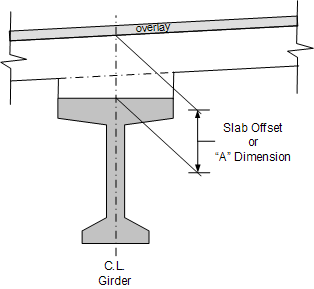
The slab offset is the vertical distance from the roadway surface to the top of girder measured at the intersection of the girder centerline and bearing centerlines at exterior permanent supports. The slab offset defines the depth of the haunch at those locations as shown in figure below for an I-Beam.
Bearing seat elevations can be computed at slab offset locations, and are defined using the top of girder elevation at erection and other geometric information including the bearing height and recess. See Bearing Seat Elevations and Locations - Geometric Assumptions for details.
NOTE: The slab offset is known in WSDOT jargon as the "A" Dimension and in TxDOT jargon as the "X" Dimension.

TIP: In PGSuper, the haunch can be defined using input of Slab Offsets only. See Haunch Depth Input: Simplified Slab Offset (PGSuper Only) for more information.
TIP: PGSuper's Girder Designer can find an optimal Slab Offset for you.
The required slab offset is the sum of the effects described in the previous chapter Haunch and Vertical Design Concepts.

The reported required slab offset is rounded up to the nearest 1/4 inch (or 5 mm) before reporting and comparison with the user-input slab offset.
The minimum value of the slab offset is

Minimum haunch depths at bearing centerlines can be optionally checked placing another requirement on the controlling slab offset. This value is defined in the girder library and is checked at both bearings as follows:

where:
is the specified minimum allowable haunch depth at bearing centerlines.
For bridges on sharp crown vertical curves, the slab haunch depth can become excessive to the point where projecting stirrups are too short to properly engage the deck reinforcement to form a composite section. Similarly the length of leveling bolts in precast deck panels may need adjustment. A warning will be added to the slab haunch specification check report when the variation in haunch depth along the precast element exceeds 2 inches.
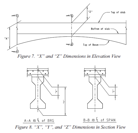
Many agencies have their own nomenclature for slab offset dimensions and TxDOT is no exception. The figure below illustrates TxDOT's "X", "Y" and "Z" dimensions. These are reported in the TxDOT Summary and Girder Schedule reports.
NOTE: that reported values for "X", "Y" and "Z" are rounded up to the nearest 1/8"
