Tacoma Narrows Bridge history - Bridge - The machine
1940 Narrows Bridge – The Machine
Designing and building the bridge that became Galloping Gertie
What's here?
- Suspension bridge design to 1940
- The engineering challenge in 1938
- Eldridge's design
- Moisseiff's design
- Building the 1940 Bridge
- "Span Stats" - Statistical profile of the 1940 Narrows Bridge
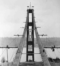
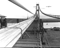
Looking west from spinning tower, showing catwalks and tram supports January 1940, WSDOT
Suspension bridge design to 1940
We live in an era of great suspension bridges. They are common today, but they have been used for centuries. The earliest forms used ropes for cables. A major advance came in 1826 with completion of the Menai Strait Bridge. The bridge became the first suspension span to use linked iron bars and chains instead of ropes. Soon, bridge builders started using wrought-iron wire for the cables.
The first use of steel and steel wire cables for a suspension bridge appeared in 1883. Steel is extremely strong and ideally suited for use in cables. In 1883 workers completed the Brooklyn Bridge. Its designer was America's most famous suspension bridge engineer, John Roebling. Roebling and his son developed methods of building foundations and spinning wire cables that we still use today.
Failures of suspension bridges occurred periodically in the 19th century. Ten suspension bridges (three in the United States and seven in Europe) either collapsed in windstorms or suffered significant damage in the seven decades between 1818 and 1889. Before the 1883 Brooklyn Bridge, people considered suspension bridges risky and unreliable. In the era when heavy railroads dominated transportation in America, other bridge types (like the steel cantilever) dominated bridge architecture.
After 1909, that began to change. The 1909 Manhattan Bridge introduced the "deflection theory" to suspension bridge design in the United States. Designer of the bridge was Leon Moisseiff, a brilliant bridge engineer and mathematician. The "deflection theory" had been formulated in Austria for concrete arch bridges. Moisseiff developed and applied the theory for suspension bridges.
The "deflection theory" was expressed in a series of mathematical formulas. The central principle held that stiffening trusses or cable-stays were not necessary. That's because the weight of the deck, main cables, and suspender cables (the "dead weight" elements) alone provided sufficient structural strength against the effects of wind and traffic. In other words, wind (aerodynamic force) was only a stress that could move the bridge laterally (sideways). Simply account for that stress by stiffening the cables or other parts, and the bridge could be light and strong.
This had a profound impact. The amount of steel needed to build suspension bridges could be hundreds of tons less than required by previous design practice. Less steel greatly reduced the cost of a bridge. By the late 1920s and into the 1930s great long-span suspension bridges were being built across the country. They were becoming longer, lighter, and narrower. These suspension bridges were theoretically sound, cheaper to build, and people considered them more beautiful.
In 1931 the George Washington Bridge became the longest suspension bridge in the world. The span raised confidence in longer, lighter, and more slender spans. The 1939 Bronx-Whitestone Bridge became the first suspension span to use a solid plate girder for the roadway-deck. Also, it was the first with rigid frame towers that had no diagonal cross bracing.
The 1940 Narrows Bridge represented a culmination of the trend to build longer bridges with a narrower road width and a minimum of stiffening.
| 1940 Narrows Bridge & Contemporaries | ||||
|---|---|---|---|---|
| George Washington | Golden Gate | Bronx-WhiteStone | Tacoma Narrows | |
| Year Completed | 1935 | 1937 | 1939 | 1940 |
| Cost | $59.5 million | $35 million | $19.7 million | $6.4 million |
| Length of center span | 3500 ft | 4200 ft | 2300 ft | 2800 ft |
| Girder Dept | 36 ft | 25 ft | 11 ft | 8 ft |
| Width (of wind truss) | 106 ft | 90 ft | 74 ft | 39 ft |
| Ratio: Girder Depth to Length (of center Span | 1:120 | 1:168 | 1:209 | 1:350 |
| Ratio: Width to Length (of center span) |
1:33 | 1:47 | 1:31 | 1:72 |
The engineering challenge in 1938
What problems did engineers face in building the 1940 Narrows Bridge? First and foremost was the geography of the Narrows itself.
The Tacoma Narrows is a difficult place to build a bridge. The water is over 200 feet deep. Swift, treacherous tides moving at over 8.5 miles per hour (12.5 feet per second) sweep through the channel four times a day.
The piers would be the deepest ever constructed, almost double the previous world record set by the 1937 Golden Gate Bridge. The major difficulty occurred in one of the earliest parts of construction, anchoring the caisson during its floating stages.
The length of the crossing, combined with the water depth, also posed difficulties. The new Narrows Bridge would become the third longest suspension span in the world, behind the Golden Gate Bridge and the George Washington Bridge.
Traffic surveys imposed the final engineering challenge. Studies showed relatively little use for the span. There was no way to justify a bridge of more than two lanes. The span over the Narrows would have to be both long and narrow.
Eldridge's design
Eldridge's design, WSDOT
Clark Eldridge, the State Highway Department's lead engineer for the project, developed the bridge's original design from late 1937 to the spring of 1938. Eldridge envisioned a suspension bridge with two traffic lanes. Other basic features included a center span of 2,600 feet; 2 side spans of 1,300 feet each; trusses and cables 39 feet center-to-center; and stiffening trusses 25 feet deep. Because the approaches differed in height (the Tacoma end was almost 20 feet higher), Eldridge designed towers of different height—the west tower at 463 feet 6 inches, the east tower at 476 feet 6 inches. Each tower had 5 bracing struts between the legs above the deck and 3 below the deck.
But, federal authorities forced critical design changes when the State Toll Bridge Authority (WSTBA) requested federal assistance from the Public Works Administration (PWA). The PWA agreed to a grant of 45 percent of the construction cost. But, they also required Washington State Authorities to hire an outside, and more prominent, suspension design consultant, Leon Moisseiff of New York, for the superstructure. Moisseiff told the PWA that his changes would cut the bridge's estimated cost from $11 million to $7 million. The substructure was to be designed by another New York bridge architectural consulting firm, Moran and Proctor. The state complied. Both consulting firms substantially changed Clark Eldridge's design.
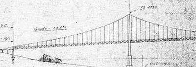
Eldridge's design; elevation detail, May 23, 1938 WSA, WSDOT records
Moisseiff's design
Moisseiff's new superstructure design became the 1940 Narrows Bridge. He used the same basic specifications for the roadway width (the distance center-to-center between cables). But, in every other respect, Moisseiff designed a very different superstructure.
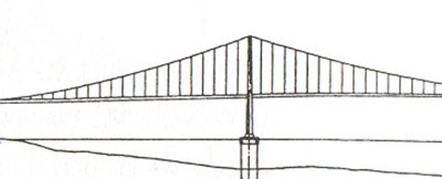
Moisseiff's design; elevation detail, 1940 WSA, WSDOT records
The side spans became 1,100 feet long, and the center span 2,800 feet long. Instead of the 25-foot deep truss deck support designed by Eldridge, Moisseiff substituted a solid 8-foot plate girder support. His design changed the towers to the
same height, 425 feet. Moisseiff also reduced the number of bracing struts joining the tower legs to 2 above the deck and 2 below. His Modernist-Art Deco design for the towers and anchorages set a new standard for suspension bridge aesthetics.
The new design created a much lighter, more flexible bridge, with a center span-to-width ratio of 1 to 72. This ratio was unprecedented, substantially beyond the Golden Gate Bridge's 1 to 47 ratio.
The 1940 Narrows Bridge became the first bridge that Moisseiff largely designed himself. Ironically, although he had helped design many of America's long suspension bridges, he never had been the primary, leading designer.
Construction contractors presented the next hurdle. When the substructure plans developed by Moran and Proctor went out to bid, contractors protested to the State Highway Department. The pier design, they said, would be impossible to build. Clark Eldridge brought out his original plans. The contractors agreed, and the PWA approved the modified plan.
The 1940 Narrows Bridge was built with Eldridge's plan for the piers and Moisseiff's design for the superstructure.
Building the 1940 Narrows Bridge
A combination of companies held the general contract: the Pacific Bridge Company of San Francisco (which was the operating company), General Construction Company of Seattle, and the Columbia Construction Company. These firms built the piers and anchorages. Bethlehem Steel Company of Pennsylvania held the sub-contract for the superstructure. John A. Roebling Sons Company of New York produced the cable wire.
Construction started on November 23, 1938. Workmen completed the bridge in only 19 months. Here is a summary of the process.
Work began with land clearing. The placement of anchors for the caissons began on January 25, 1939. By March 18, 1939 tugboats towed the first caisson to the Narrows from the Seattle docks where they had been built. Meanwhile, excavation for the anchorages began and was completed in mid-May. Pier construction was completed on July 13 for the west pier and September 15, 1939 for the east pier. Tower construction was completed between August and November 1939. Cable spinning began in January 1940 and ended a month later. By March the first section of steel for the roadway-deck system was placed, as workmen raced toward the scheduled June 30 completion date. With a completion rate of 200 feet per day, the steel floor system (girders, beams and stringers) was finished by May 6. Concrete work began immediately and was completed by June 10th, at an average of 300 feet per day.
Several features of the bridge drew special interest. Pier construction (Pier 4, or West Pier, and Pier 5, or East Pier) proved to be the most difficult ever attempted. They were built at a world-record depth. Swift tides up to 12.6 miles per hour created a dangerous environment that required creative engineering solutions. The fast tidal currents shifted constantly and created treacherous swirling action around the caissons. The East Pier (Pier 5) was the more difficult of the two. The caisson's cutting edge touched bottom at 140 feet, then penetrated another 90 feet into the Narrows sea floor. Final height of the East Pier measured 247 feet. From start to finish, pier construction took from December 15, 1938 to September 15, 1939.
Finally, on the prescribed completion date of June 30, 1940 workmen finished the concrete roadway, sidewalks, and curbs. Painting the steel superstructure started in mid-April and was largely finished by the end of June, but dragged on for several more months. On July 1, 1940 the first Narrows Bridge stood ready for official opening ceremonies.
Anchors for caissons
In order to hold the caissons steady against the current, engineers and workmen dumped concrete anchors measuring 12 feet-by 12 feet-by 51 feet 6 inches. These were distributed in a 900-foot diameter circle around the caisson and attached to it by cables of 1-9/16 inch diameter. For the East Pier (Pier 5) 32 anchors were required and 24 anchors for the West Pier (Pier 4). Each anchor weighed approximately 600 tons.
Piers - caissons
The caissons, consisting of steel trussing and girders arranged within wooden sheathing, measured roughly 66 feet x 119 feet. They were built up to 36 feet in height off-site, then towed to the Narrows. At the base was the sharp metal cutting edge. Once tugboats positioned the caisson, workmen began pouring concrete. The caisson sank under its own weight to a point where workers built a 12-foot high wooden hull at its top, with a steel framework and partitions. Then, concrete pouring began.
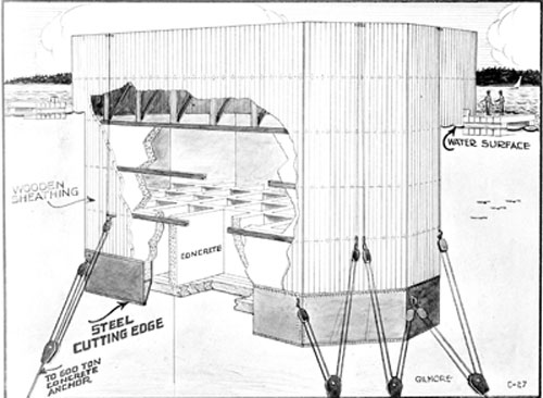
Caisson cross-section drawing, 1939 WSDOT
The swift tides made holding the construction barges with concrete next to the caissons difficult and dangerous. Sometimes, one end of a caisson would be 8 feet lower in the water than the other.
The three-month process was repeated in 12-foot layers until the cutting edge reached the floor of the Narrows. Then, workers removed boards in the caisson's bottom section and started excavation. Clamshell buckets scooped away compacted gravel, sand, and mud, lifting it up through the caisson's hollow concrete cells to the surface. Slowly, the caisson sank to the desired depth for a solid pier foundation. Finally, workers placed a concrete cap on each pier.
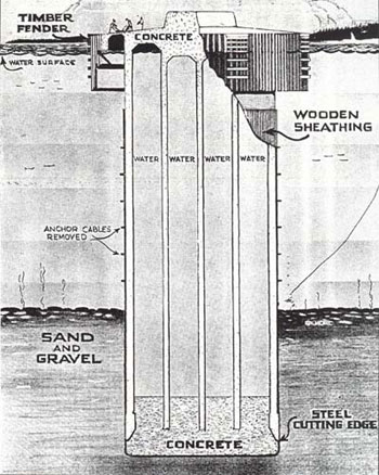
Pier cross section drawing, 1939 WSDOT
Anchorages
Meanwhile, construction of the anchorages proceeded. Beginning in late March 1939, workers removed tons of soil from the designated area on the Narrows bluffs. Then, they poured tons of concrete for the main body of the anchorages. Next came placement of the eye-bars. By the third week of May, construction of the anchorages was suspended until completion of cable spinning.
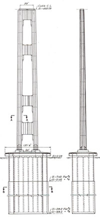
Tower face and side view, drawing, 1939 WSDOT
Towers
Then, tower erection began. The 425-foot tall towers were made of structural carbon steel plates (mostly ½-inch). Workmen riveted the plates into place, arranging them in a cross-like section. The towers were braced by 4 horizontal struts, 2 above the deck and 2 below the deck. Engineers had designed the towers to be bent toward shore 3 feet during construction, and 3 inches in their final dead-load positions. Each tower's legs were spaced 50 feet apart (center-to-center) at the base, and 39 feet apart (center to center) at the top.
At the top of the towers was another important innovation. The 1940 Narrows Bridge was the first suspension bridge to use all-welded cable saddles. (Previous spans used cast steel.)
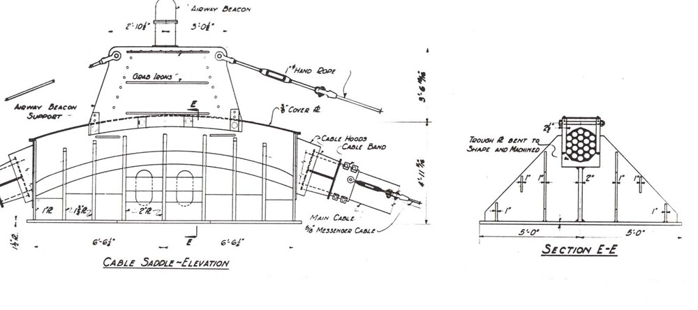
Cable saddle drawing, 1939 WSA, WSDOT records
Once the towers were completed, workers built catwalks. Next came spinning of the main cables, then deck construction. Suspender cables attached the main cables to the deck at 50-foot intervals with zinc connectors, called "jewels."
Cable Spinning
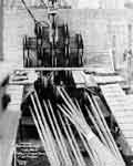
Giant reels of steel wire with a thickness of the average pencil waited at the east anchorage. A boat took the first wire across the water. Then, workmen hoisted the wire to the top of one tower. They repeated the process for a second wire. The two wires then were joined together to make a "traveler rope."
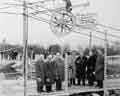
January 10, 1940 start of cable spinning WSDOT
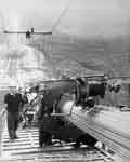
Construction of west anchorage showing cable spinning, January 1940 WSDOT
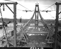
Cables and catwalks, view from west, January 1940. The copyright in this image is the property of the Tacoma Public Library. Any additional copies or reproduction of this image are prohibited. All rights reserved
At each anchorage, the traveler rope was fitted with a "spinning wheel" and looped over a pulley. One end of wire from a spool was secured to an eye-bar (or "I-bar") at the anchorage and looped around the spinning wheel. The spinning wheel followed the moving traveler rope up over the towers at the cable saddle and across the water to the anchorage on the opposite shore.
Cable compacting, 1940 WSDOT. The copyright in this image is the property of the Tacoma Public Library. Any additional copies or reproduction of this image are prohibited. All rights reserved
View of cable spinning underway from west end, January 1940. The copyright in this image is the property of the Tacoma Public Library. Any additional copies or reproduction of this image are prohibited. All rights reserved
When the desired number of wires accumulated, workers collected them into a "strand." Then, they compacted the strands and wrapped them with wire to complete the main suspension cable.
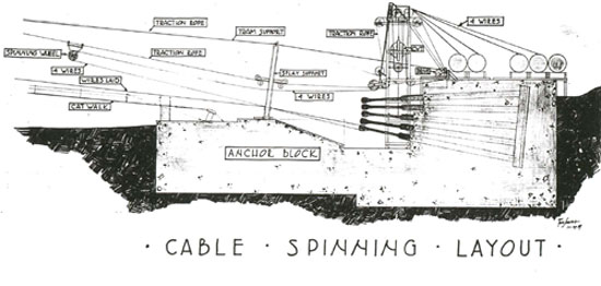
Cable Spinning Layout, drawing, 1939 WSA, WSDOT records
Suspender Cables and Cable Bands
Four vertical suspender cables (also called "hanger" cables, or hanger "ropes") made of twisted wire were placed at 50-foot intervals along the main cable and deck. Workmen attached the suspender cables to the main cable and deck with cable bands. Next, they wrapped the main cables with steel wire for protection against the elements. Workmen hammered lead wool into the joints and openings around the cable bands to make a watertight fit.
Road deck drawing, 1940 WSA, WSDOT records
Deck-roadway
Deck construction made use of pre-formed sections. The stiffening girder (1-7/8 inch plate steel) and deck sections were pre-assembled in Seattle. Scows carried the sections to the construction site. Then, cranes with Chicago booms hoisted the sections into place, where they were riveted. One of the interesting bits of on-site ingenuity was prompted when workers had trouble fitting the girders into place. The solution—the adjoining pieces were packed in dry ice, causing them to contract. They could then be fitted together and riveted into place. The 1940 Narrows Bridge was only the second suspension bridge to use a solid plate girder. (The first was the Bronx-Whitestone Bridge in New York, designed by Othmar Amman, with Leon Moisseiff as design consultant.)
During construction, an earthquake struck on November 13, 1939. At 7:45 a.m. the strongest earthquake in decades struck the region. The jolt of 6.2 magnitude, with an epicenter some 6 miles south of Bremerton, shook the Narrows Bridge. When engineers investigated, they were relieved to find no damage to the towers.
Finally, by April 1940 painting began. The bridge received three coats of "Narrows Green" paint.
The people who built the bridge
"Span Stats" - Statistical profile of the 1940 Narrows Bridge
| Length: 1940 Narrows Bridge | |
|---|---|
| Length: | 1940 Bridge |
| Total Structure Length | 5,939 feet |
| Suspension Bridge Section | 5,000 feet |
| Center Span | 2,800 feet |
| Shore Suspension Spans (2), each | 1,100 feet |
| East Approach and Anchorage | 345 feet |
| West Approach and Anchorage | 594 feet |
| Anchorage: 1940 Narrows Bridge | |
|---|---|
| Anchorages (shore anchors) | 1940 Bridge |
| Weight of each anchorage | 52,500 tons |
| West Anchorage (concrete anchor block and gallery) | 20,250 cu. yds. |
| Concrete in each anchorage | 20,000 cu. yds. |
| Structural steel in each anchorage | 592,500 lbs |
| Cable Anchor Bars | 38 in each anchorage, 9,700 lbs. each, 54' long |
| West Anchorage (concrete anchor block and gallery) | 169' long, 70' wide, 66' deep |
| East Anchorage (concrete anchor block and gallery), plus approach, administration buildings and toll house | 173' long, 70' wide, 50' deep |
| West Anchorage, construction & cost | Woodworth & Cornell, Inc. - $299,734 |
| East Anchorage, construction & cost | Pacific Bridge Co. - $272,273 |
| Piers: 1940 Narrows Bridge | |
|---|---|
| Piers | 1940 Bridge |
| Number of caisson anchors, east pier | 32 |
| Number of caisson anchors, west pier | 24 |
| Weight of each caisson anchor | 570 tons |
| Size of caisson anchors | 12 X 12 X 51 feet by 6 inches in 900 foot diameter circle around caisson |
| Area | 118 feet, 11 inches by 65 feet, 11 inches |
| West Pier, total height | 198 feet |
| West Pier, depth of water | 120 feet |
| West Pier, penetration at bottom | 55 feet |
| East Pier, total height | 247 feet |
| East Pier, depth of water | 140 feet |
| East Pier, penetration at bottom | 105 feet |
| Reinforced concrete in piers | 111,234 cu. yds. |
| Distance between piers | 2,700 feet |
| Distance to shore from east pier | 650 feet |
| Distance to shore from west pier | 1,030 feet |
| Construction cost, West Pier (#4) | $1,126,003 |
| Construction cost, East Pier (#5) | $1,275,723 |
| Total pier construction cost | $2,401,726 |
| Cables: 1940 Narrows Bridge | |
|---|---|
| Cables | 1940 Bridge |
| Diameter of Main Suspension Cable | 17.5 inches |
| Weight of Main Suspension Cable (each) | 3,817 tons |
| Weight Sustained by Cables | 11,250 tons |
| Sag ratio (elevation drop per foot) | 1:12 |
| Number of No. 6* Wires in Each Cable | 6,308 |
| Number of wire strands in each cable | 19 |
| Number of No.6 wires in each strand | 332 |
| Number of wires carried by spinning wheel per trip | 8 |
| Time needed by spinning wheel to cross Narrows per trip (one/way) |
10 minutes |
| Number of reels of wire | 440 |
| Length of wire in one strand | 370 miles |
| Total Length of Wire | 74,926,424 feet, = 14,191 miles |
| Cost of cables and fittings, both cables | $1,335,960 |
| *Wire: No. 6 size, high carbon manganese silica steel. | |
| Towers: 1940 Narrows Bridge | |
|---|---|
| Towers | 1940 Bridge |
| Height above water | 443 feet |
| Height above piers | 425 feet |
| Height above roadway | 230 feet |
| Weight of each tower | 1,927 tons |
| Legs (2 per tower) at base, each | 19 feet 1-1/2 inches by 13 feet 5-1/2 inches |
| Legs (2 per tower) at top, each | 13 feet by 113 feet 39 feet apart |
| Time to construct, west tower (#4) | 25 days (8-hour/day) |
| Time construct, east tower (#5) | 21 days (8-hour/day) |
| Cost of both towers | $542,144 |
| Deck: 1940 Narrows Bridge Comparison | |
|---|---|
| Roadway - deck | 1940 Bridge |
| Center Span Height Above Water | 195 feet |
| Weight of center span | 5,700 lb./ft |
| Traffic lanes | 2 |
| Width of Roadway | 26 feet |
| Width between Cables | 39 feet |
| Width of Sidewalks(2), each | 5 feet |
| Number of girders and type | 2 plate girders |
| Depth of girders | 8 feet |
| Suspender cables | 50 foot intervals |
| Thickness of roadway | 5-1/4 inch reinforced concrete |
| Materials: 1940 Narrows Bridge | |
|---|---|
| Materials | 1940 Bridge |
| Structural Steel | 20,665,000 lbs |
| Reinforcing steel | 3,654,000 lbs. |
| Cable wire and fittings | 8,500,000 lbs. |
| Concrete | 103,129 cu. yds. |
| Concrete pavement (roadway) | 5,200 sq. yds. |
| Timber for pier fenders - treated | 430,000 bd. ft. |
| Timber for pier fenders - untreated | 720,000 bd. ft. |