|
PGSplice
3.0
Precast-prestressed Spliced Girder Bridges
|
|
PGSplice
3.0
Precast-prestressed Spliced Girder Bridges
|
The general layout of the spliced girders is defined in the bridge description. The location of the piers, temporary supports, and closure joints define the number and layout of the precast segments. The basic cross sectional dimensions of a girder are defined in the Girder library. The following information is needed to complete the girder definition:
This additional information is defined through the Girder Details window.
To define your girder:
Press [Edit], for a segment row, in the Segments grid to open the Segment Details window.
To define your segment:
The basic cross sectional shape of the segment is defined by its associated Girder library entry. The shape of the segment in elevation is defined in the Section Variations group on the General tab.
The Girder library entry defines if segments can vary in depth or if they must be constant depth. For variable depth girders, four variation types are available; Linear, Parabolic, Double Linear, and Double Parabolic. These variations are illustrated below.
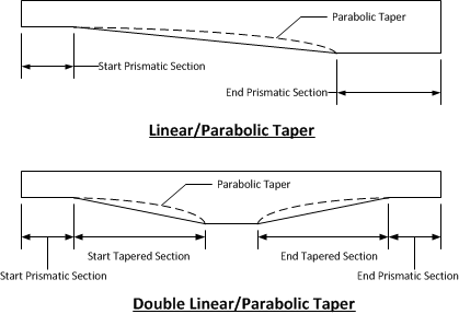
The variation in segment depth is defined by the left of a prismatic (constant depth) section at the start and end of the segment. These sections are defined by their length and the overall segment depth. For Linear and Parabolic variations, the segment tapers in depth between the two prismatic sections. The parabola is always tangent to the bottom of the segment at the shallow end.
Double Linear and Double Parabolic variations are used to define haunched segments with two variations. In addition to the prismatic sections at the ends of the segment, the tapered sections are defined by their length and height. A linear taper in segment depth connects the ends of the start and end taper segments.
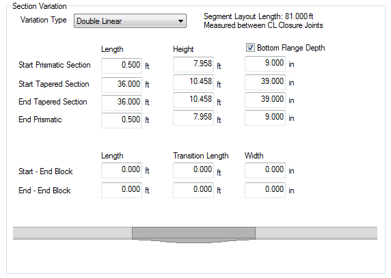
Some girder types support variable depth bottom flanges. This is common with I-Beam type sections. The bottom flange depth can be defined for the prismatic and tapered sections.
Some girder types support end blocks. End blocks are defined by their length, transition length, and width at the end of the girder. End blocks are a constant width for their length, and then transition back into the typical girder section over the transition length.
TIP: The sketch of the segment updates as dimensions are changed. The dark gray segment is the current segment and the light gray segments are the adjacent segments. This image will show you how changes to this segment effects the adjacent segments.
Since PGSplice is using a non-linear time-step analysis, time-dependent material models are needed for concrete. The material model needs to define concrete strength and modulus of elasticity as a function of time.
The general concrete material model is defined in the Project Criteria. The model is then customize for each piece of concrete in the bridge. To define the material model for a segment:
See Time-Dependent Material Models in the Technical Guide for more information about the time-dependent concrete material models.
Press [Edit], for a closure joint row, in the Segments grid to open the Closure Joint Details window.
To define your closure joint:
The post-tensioning ducts and tendons are defined in the Ducts/Tendons grid. Use [Add] and [Delete] to manage the ducts.
To define a duct and tendon:
TIP: The sketch of the girder shows the overall girder profile and the duct geoemtry. This example shows a 4 span girder made up of 7 variable depth segments with parabolic ducts.

NOTE: Ducts must run the full length of the girder. Partial length ducts are not supported at this time.
 1.8.11