|
PGSuper 8.0
Precast-prestressed Girder Bridges
|
|
|
PGSuper 8.0
Precast-prestressed Girder Bridges
|
|
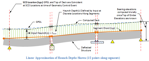
As discussed in Haunch Depth Input: Explicit Direct Method, explicit input can be used to directly define haunch depths along segments or spans (i.e., generalized Haunch(x)) in a piecewise linear or parabolic manner. As the figure below demonstrates, computed deck elevations along a girderline can be easily determined once top of deflected girder elevations are known.

The remainder of this document describes how deflected girder top elevations are computed.
The LBAM (Longitudinal Bridge Analysis Model) in PGSuper and PGSplice is based on a 1D flat beam model analysis that occurs from the time of first segment erection onward. Unrecoverable deformations prior to the time of erection are also included in the LBAM response. To determine elevations along CL girders in the deflected bridge model, deflections from the flat model must be mapped into curvilinear bridge elevations defined by roadway profile elevations, haunch depth input, and temporary support elevation adjustments. This mapping is performed by summing deflection results from the 1D LBAM model at the time of GCE with elevations of a segment chord line along the girder.
The mapping from 1D LBAM deflections into deformed bridge elevations is briefly outlined as follows. Further details are presented later.
The above mapping establishes deformed elevation results at the time of the GCE. Subsequent results are computed by adding incremental LBAM 1D deflections to the GCE elevations. Deformed elevations prior to the GCE are computed by subtracting prior incremental LBAM deflections from the established GCE elevations.
Locations of SCD’s are not directly input but are computed based on bridge model geometry and boundary conditions present at the of the Geometry Control Event.
Rules to Determine SCD Locations:
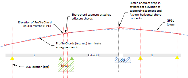
SCD locations are shown by vertical red lines in the sketches below.

The Profile Chord line lies along the GPGL with each chord terminating at SCD locations at GPGL elevations as shown in the figure below.

The geometry of the segment chord is established at the time of the Geometry Control Event (GCE). Elevations along the unadjusted segment chord are established at Segment Chord Datums (SCD’s). Rules used to determine SCD locations were defined previously.
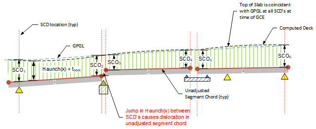
Chord elevations at SCD’s are computed by subtracting a Segment Chord Offset (SCO) from the roadway elevations on the GPGL as shown below. Haunch(x) is defined by user input haunch depths along girders.
SCO = Haunch(x) + Deck Thickness, at each SCD location.
The figure below illustrates an example unadjusted segment chord layout.

Note in above example: When a jump occurs in Haunch(x) at an SCD at a closure, there is a corresponding dislocation in the unadjusted segment chord, which causes a dislocation in top of girder elevations. When this occurs, elevations in the closure between the segment ends will be linearly interpolated between the end elevations.
The previous steps describe establishment of the unadjusted segment chord based on elevations and haunch depths and haunch depths at SCD locations. In PGSplice, segment chords can be further adjusted by user-input elevation adjustments at temporary supports at closure joints.
Elevation adjustments are applied directly to the ends of segment chords at closure joints. This will adjust the elevations computed at the Geometry Control Event (GCE). Note that any adjustments will cause the deck elevation to not match the profile grade (GPGL) at the GCE. However, adjustments may be desirable for "tweaking" final finished elevations to fit project-specific requirements.

Deflected top of girder elevations can be computed once adjusted segment elevations have been determined. The mapping process is detailed in Mapping of 1D Deflections to Deformed Top of Girder Elevations.
As discussed previously, roadway elevations are computed by simply adding haunch + deck depths to the deflected top of girder elevations.