|
PGSuper 7.0
Precast-prestressed Girder Bridges
|
|
PGSuper 7.0
Precast-prestressed Girder Bridges
|
Parameters that control the flexural design of this girder type are defined on this tab. Parameters include debonding limits, location of debonding sections, and the strategies that are to be used for service limit state design.
These parameters establish limitations on strand debonding.
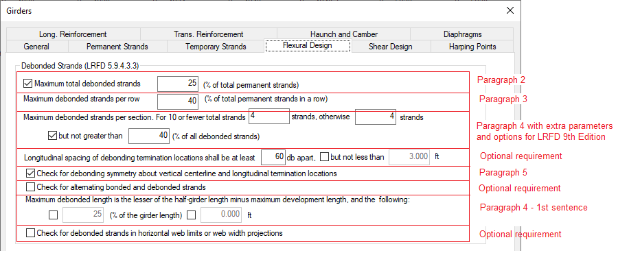
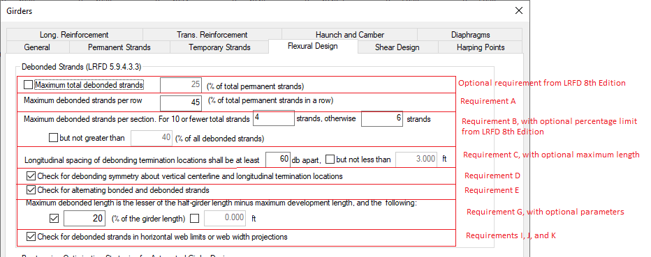
NOTE: Debonding requirements were significantly changed in the AASHTO LRFD Bridge Design Specifications, 9th Edition, 2020. The parameters defined in this section can be configured to reflect LRFD 8th Edition and earlier, LRFD 9th Edition and later, and many Owner/Agency requirements that deviate from AASHTO LRFD. See examples of parameters below.
NOTE: The flexural design algorithm does not attempt to position debonded strands to satisfy the requirements of LRFD 9th Edition 5.9.4.3.3 Requirements E, 4th bullet of Requirement I, 1st bullet of Requirement J, or 1st bullet of Requirement K, though these requirements are evaluated in the specification check. Careful selection of the debondable strands when defining strand grids will result in better design outcomes.
| Item | Description | LRFD 9th Edition 5.9.4.3.3 Requirement | LRFD 8th Edition 5.9.4.3.3 Paragraph |
|---|---|---|---|
| Maximum total debonded strands | When checked, limits the total number of debonded strands as a percentage of the total number of strands. A limit of 25% was recommended in LRFD 8th Edition and earlier. The limit was removed in LRFD 9th Edition because research shows a greater number of strands can be debonded. | - | 2 |
| Maximum debonded strands per row | Enter this value as a percentage of the number of permanent strands in a row. | A | 3 |
| Maximum debonded strands per section | These values limit the number of strands that can be debonded at a given longitudinal location. Starting with LRFD 9th Edition, there is a maximum number of debonded strands per section for girders with 10 or fewer debonded strands and a maximum number for all other cases. In LRFD 8th Edition and earlier, the limit on the number of strands that could be debonded was a number of strands (4) but the total number of debonded strands was constrained to a percentage of the total number of strands (40%). The 8th Edition and 9th Edition requirements can be modeled. | B | 4 |
| Longitudinal spacing of debonding termination locations ... | Enter the minimum distance between debonding termination locations as a number of strand diameters. Optionally, a minimum distance can be specified. This distance should not be less than the prestress transfer length. | C | - |
| Check for debonding symmetry about vertical centerline and longitudinal termination locations | When checked, the debonding arrangement is evaluted to ensure debonded strands are symmetrically distributed about the vertical centerline of the cross section of the member and debonding is terminated symmetrically at the same longitudinal section. See note below. | D | 5 |
| Check for alternating bonded and debonded strands | When checked, the debonding arrangement is evaluated to ensure bonded and debonded strands locations are alternated both horizontally and vertically. See note below. | E | - |
| Maximum Debond Length | The maximum distance from the end of a precast element to the farthest debond termination location cannot exceed lesser of:
| G | - |
| Check for debonded strands in horizontal web limits or web width projections | When checked, the arrangement of debonded strands is evaluted to ensure strands are bonded within the horizontal limits of the web (Requirement I, first and second bullets - See LRFD Figure C5.9.4.3.3-1) or within the web width projection (Requirement J, second bullet - See LRFD Figure C5.9.4.3.3-2). | I and J | - |
NOTE: LRFD 9th Edition, 5.9.4.3.3 Requirement D is not evaluated, regardless of the setting described above, when the Define Individual Strands method is used to define the pretensioning in a precast member. You will need to evaluate compliance with this requirement by other means.
NOTE: LRFD 9th Edition, 5.9.4.3.3 Requirement E, the requirement is to alternate bonded and debonded strand locations both horizontally and vertically. In order to do this, 50% of the strands must be deboned. This is not the intent of the requirement. The intent is to ensure debonded strands are not adjacent to one another, horizontally or vertically. This requirement is evaluated by checking the adjacentcy of debonded strands.
NOTE: LRFD 9th Edition, 5.9.4.3.3 Requirement F, (LRFD 8th Edition, 5.9.4.3.3, paragraph 1) a value of k=2.0 is always used when determining the development length of debonded strands.
NOTE: LRFD 9th Edition, 5.9.4.3.3 Requirement H is not evaluated. LRFD 5.12.3.3.9a does not permit debonded strands to be used for positive moment connections at continuity diaphramgs.
NOTE: For girder sections where LRFD 9th Edition, 5.9.4.3.3 Requirements I and J are applicable, the horizontal limits of the web and the web width projection are shown graphically on the girder cross section in the Girder Library.
NOTE: LRFD 9th Edition, 5.9.4.3.3 Requirement I fourth bullet, Requirement J first bullet, and Requirement K first bullet are not evaluated.
NOTE: LRFD 8th Edition, 6th paragraph and LRFD 9th Edition Requirement I third bullet, Requirement J third bullet, and Requirement K second bullet are always evaluated. Only outer-most (exterior) strands in exterior webs or stems are evaluated for LRFD 8th Edition. For LRFD 9th Edition, when Requirement K is applicable, the outer-most strand in each stem or web is evaluated.
Use the controls in this group to direct PGSuper's prestress Girder Designer which strategies to use for the girder type in question. Strategies are attempted from top to bottom in the order shown on the dialog until a successful design is found, or all strategies are exhausted.
Refer to Advanced Flexural Design - Multiple Prestress Optimization Strategies in the User Guide for more information