|
PGSuper 7.0
Precast-prestressed Girder Bridges
|
|
PGSuper 7.0
Precast-prestressed Girder Bridges
|
Define each strand individually, ignoring the strand locations defined in the Girder Library. Asymmetric strand arrangements can be defined with this option.
NOTE: LRFD 9th Edition 5.9.4.3.3, Requirment D is not evaluated when this option is used.
| Item | Description |
|---|---|
| Strand Grid | Strand rows are defined in this grid. See below for details. |
| [Add] | Add a strand row |
| [Remove] | Remove the selected strand row |
| Permanent Strands | Select the permanent strand size and type from the drop down list. If the permanent strands are epoxy coated, check the "Grit impregnated epoxy coating" box. See Epoxy Coated Strands in the Technical Guide for more information. |
| Temporary Strands | Select the temporary strand size and type from the drop down list. Temporary strands are never epoxy coated. |
| Pjack | For each strand type, the maximum jacking force is shown. Check the box to enter a different jacking force. |
NOTE: 0.62" and 0.7" Diameter strand capabilities should be considered as experimental features. See Prestressing Steel in the Technical Guide for more details
Strands are defined in horizontal rows. Multiple rows can be defined at the same elevation in the girder section. You must ensure the clear distance between strands is acceptable. The information in the strand row grid is:
| Item | Description |
|---|---|
| Type | Use the drop down list to select the strand type. |
| Z | Horizontal location of the strand in the girder cross section, measured from the vertical centerline. |
| Left End, Y | Elevation of the strand row at the left end of the girder. |
| Left End, Face | Use the drop down list to select the face of the girder Y is measured from. |
| Left Harp Pt, Y | Elevation of the strand row at the left harp point of the girder. |
| Left Harp Pt, Face | Use the drop down list to select the face of the girder Y is measured from. |
| Right Harp Pt, Y | Elevation of the strand row at the right harp point of the girder. |
| Right Harp Pt, Face | Use the drop down list to select the face of the girder Y is measured from. |
| Right End, Y | Elevation of the strand row at the right end of the girder. |
| Right End, Face | Use the drop down list to select the face of the girder Y is measured from. |
| Ext. Strands, Left | Check if the strands are extended at the left end of the girder. |
| Ext. Strands, Right | Check if the strands are extended at the right end of the girder. |
| Debond, Left | Check if the strands are debonded at the left end of the girder. Enter the debond length. |
| Debond, Right | Check if the strands are debonded at the right end of the girder. Enter the debond length. |
Harped strands can have up to four deviation points. The images below illustate the two typical harp point layouts.
| Item | Description |
|---|---|
| X1 | Enter the distance from the left end of the girder to the first strand deviation point. Use the drop down list to select the measurement unit. |
| X2 | Enter the location of the left harp point from the left end of the girder. Use the drop down list to select the measurement unit. |
| X3 | Enter the location of the right harp point from the left end of the girder. Use the drop down list to select the measurement unit. |
| X4 | Enter the distance from the left end of the girder to the last strand deviation point. Use the drop down list to select the measurement unit. |
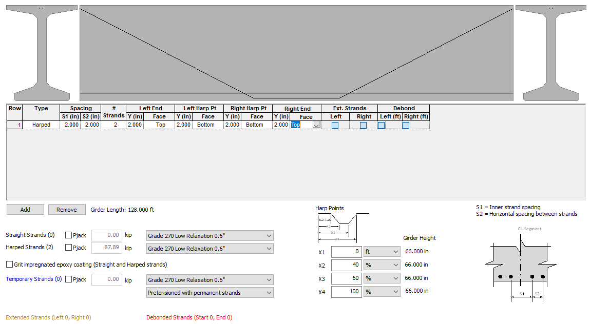 (Typical two point harped strand. Left Harp Pt Dist = 0%, Right Harp Pt Dist = 100%)
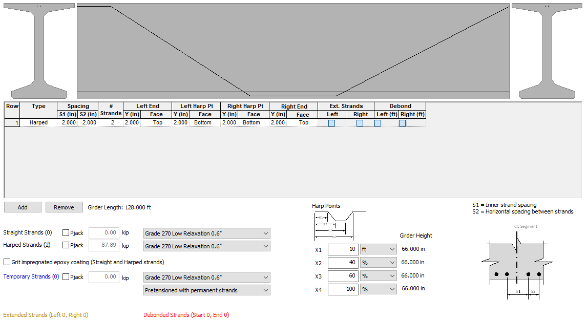 (Typical three point harped strand. This strand arrangement could be used if the left end of the girder were a cantilever. Another strand deviation could be added at the right end of the girder by changing the Right Harp Pt Dist value)