PGSuper 7.0
Precast-prestressed Girder Bridges
Bearing Seat Elevations and Locations - Geometric Assumptions

PGSuper and PGSplice can provide an accurate computation of bearing seat elevations and other bearing geometry information based on input bridge geometry. The figures in the section describe how bearing locations are computed.

The following figure shows a plan view at a generic girder/pier intersection.

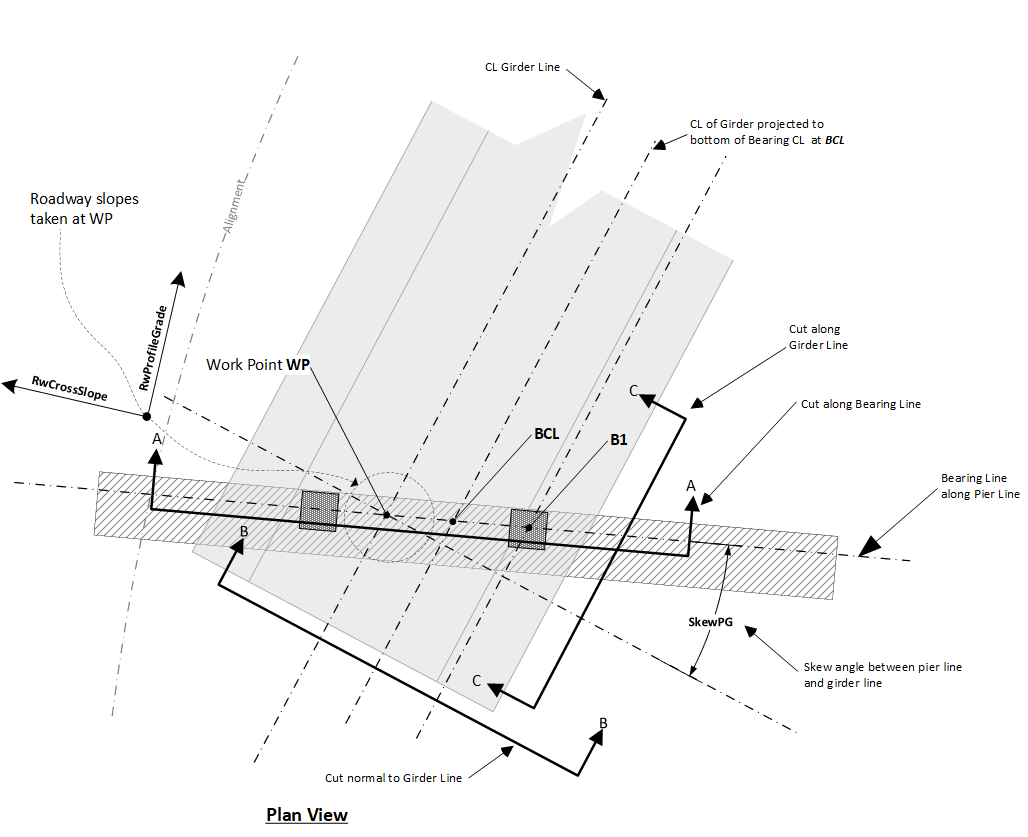
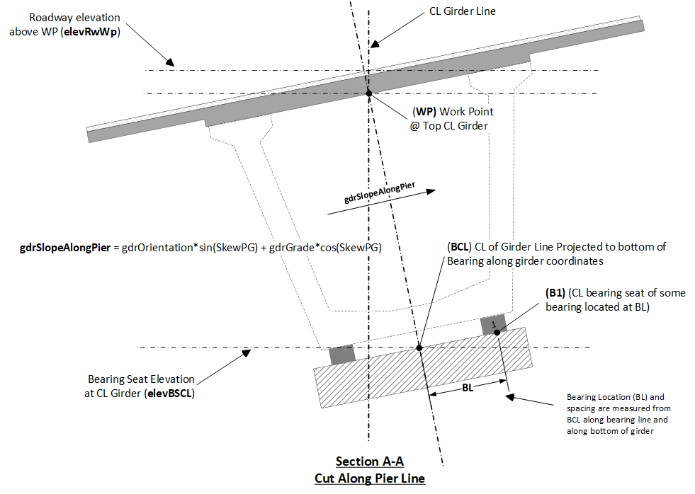
The figure below shows a section view cut along the Pier Line (Section A-A). Note that bearing spacing is laid out along the bearing line from the BCL location as shown in the figure. From this, there are a couple of observations that should be noted:

  1. When girder spacing is measured at the top centerline of the girder (i.e., the WP), the centerline bearing spacing may not be the same as girder spacing.
  2. The BCL is the center of the bearing layout and is generally not directly below the work point. Effects from profile slope, superelevation, differences in "A" dimensions along girder, and pier skew will change the BCL location when viewed in plan. However, the BCL always lies along the bearing line.
  3. Spacing between multiple bearings are measured and oriented along the bearing line as shown and is not measured along a level plane.
  4. The location of multiple bearings are assumed to be symmetric about the BCL point.

The figure below shows section cuts normal to (Section B-B) and along the girderline (Section C-C).

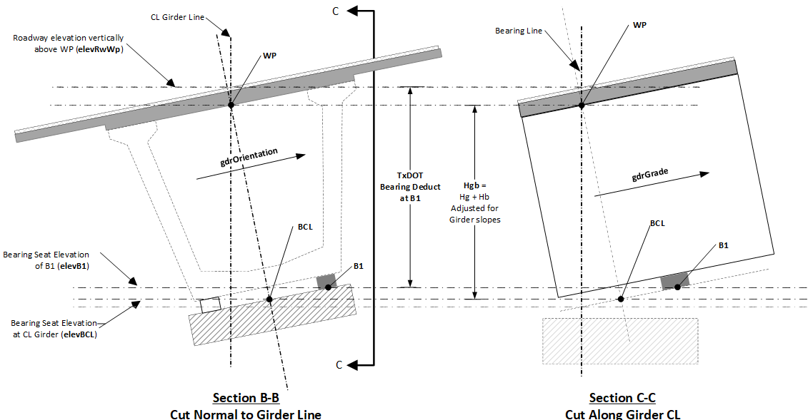
The plan view point coincident with B1 is located as shown in the figure below.

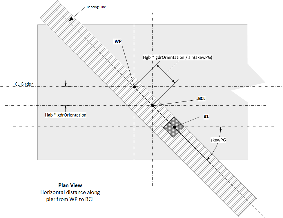
The station, offset, and roadway surface elevation are computed for this point. The bearing seat elevation is then computed as

\[ elev_{B1} = elevRW_{B1} - H_{gb} \]

where

\( elev_{B1}\) = top of bearing elevation

\( elevRW_{B1} \) = roadway surface elevation above center point of bearing B1

\( H_{gb} = (H_g + H_b)/( cos(gdrOrientation) cos(gdrGrade) ) \)

\( H_g \) = height of girder

\( H_b \) = thickness of bearing