|
PGSuper
6.0
Precast-prestressed Girder Bridges
|
|
PGSuper
6.0
Precast-prestressed Girder Bridges
|
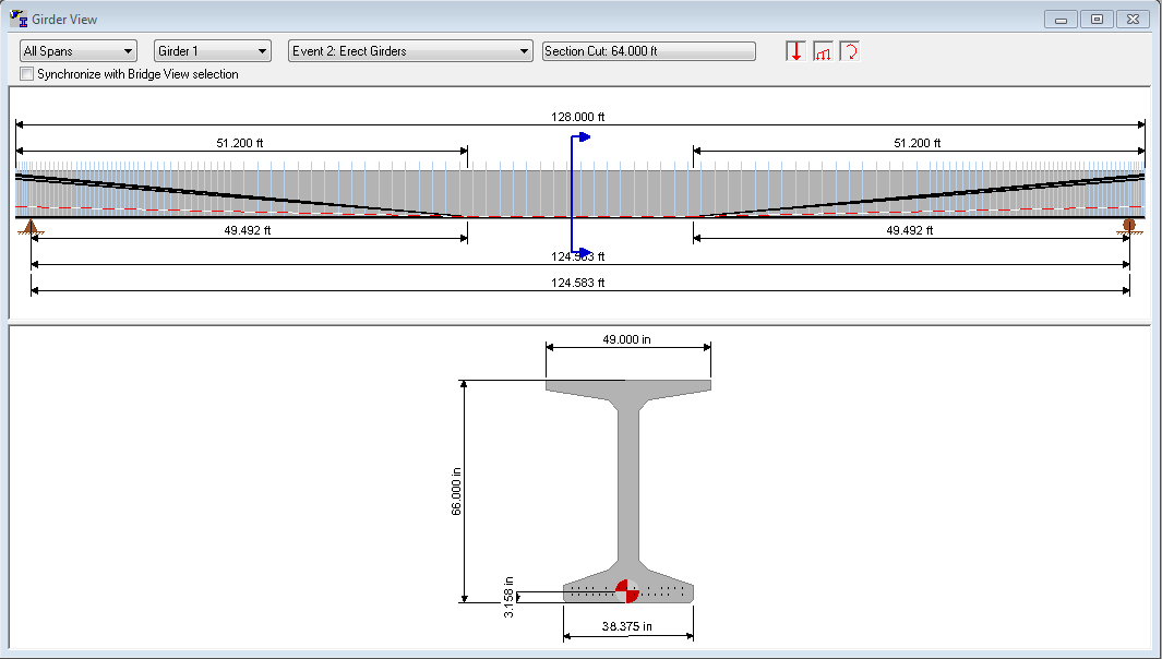
The Girder View provides a graphical representation of a girder. The view is divided into three regions, the Control Bar, the Elevation View, and the Section View.

The Control Bar is located at the top of the view. The Control Bar is used to control the contents of the Girder View.
To select a girder to view:
Use the drop down list to select the construction event for the view. The girder and applied user defined loads are shown for this event.
User defined loads can be managed in the Girder View. If user defined loads are present on the selected girder and applied in the select Construction Event, they will be displayed graphically in the elevation view.
To create a new load, drag the point load, distributed load, or moment load icon from the control bar onto the girder at the location near where you want to apply the load. Once the load is dropped onto the girder, its editing window will be opened so you can provide specific information about the load.
Loads may then be edited by right-clicking on them an selecting Edit Load from the context menu or by simply double-clicking on them.
The Legend helps define the load cases that user defined loads are applied in. You can move the legend around the view by dragging it and you can change the number of rows shown in the legend by right-clicking on it.
NOTE: Showing user defined loads and the legend can be toggled on and off. If these items are not being displayed, the view settings probably need to be enabled. See Girder View Settings for more information.
NOTE: See Loading in the User Guide for more information about User Defined Loads.
The Elevation View shows the a representation of the girder elevation. This view shows the bearing points, span length, girder length, location of harping points, prestressing strands, longitudinal reinforcing steel, and the C.G. of the prestressing force.
There are several methods for selecting a cross section in the Girder View.
Use any of the following to select a cross section:
Options 1 and 2 opens the Girder View Section Cut window. Using the slider, select a location for the section cut.
The Section View displays the girder cross section at the section cut location. The section can include the location of the prestressing strands and longitudinal reinforcing steel, the C.G. of the prestressing force, and the height and width dimensions of the girder.
You can quickly edit any of the girder attributes by selecting an attribute category from the context menu. The context editing commands will take you directly to the appropriate location in the Girder Details window.
Other options are available from the context menu as well, including Girder Design, creating user defined loads, selecting a cross section, and reporting.
TIP: To quickly edit the girder, double click anywhere in the view.
The Girder View can be customized by enabling and disabling the various options.
To customize the view select View > View Settings > Girder View. This will open the View Settings window. Customize the elevation and section views by enabling and disabling the various options on their respective tabs.
The dimension line for the width of a composite deck slab shows the tributary flange width. In most cases, the tributary flange width is equal to the effective flange width. However, if the slab overhang exceeds S/2 the effective flange width may be limited. When this occurs, the dimension lines for the tributary flange width will appear wider than the deck slab (see figure below). The tributary and effective flange widths are listed on the left side of the view.
