|
PGSuper
6.0
Precast-prestressed Girder Bridges
|
|
PGSuper
6.0
Precast-prestressed Girder Bridges
|
Lateral deflections occur in precast-prestressed concrete girders due:
NOTE: Lateral deflection of girders only occurs prior to the girder becoming connected to adjacent girders forming the bridge cross section. That is, there is no additional lateral deflection once the girder is no longer an independent structural component.
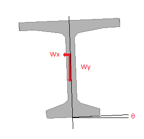
Many girder types, such as slabs, boxes, tubs (U-beams), and shallow decked bulb tee girders, are installed with a rotated orientation that aligns the top of the girder with the roadway cross slope. When installed, the rotation of the girder introduces a lateral component of load that causes lateral deflection. These are typically small deflections, however for long spans and girders without significant lateral stiffness these deflections can become sizable. The girder section shown below is installed with a rotated orientation. The load component wx causes lateral deflection.


Some girder sections, such as the decked bulb tee, are constructed with the top flange sloped to match roadway cross slope. This results in an asymmetric section. For this case, there are two sources of lateral deflection.
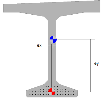
The girder section shown below is asymmetric. The principle axes are not aligned with the vertical and horizontal axes and the product of inertia, Ixy, is non-zero. This results in a component of lateral deflection due to the vertical loads. Additionally, the centroid of the prestressing force (red/white target) is eccentric with respect to the center of mass of the section (blue/white target). This results in lateral deflection due to prestressing as well as a vertical deflection component due to the asymmetry of the section.

The total deflection is the sum of direct and indirect deflections. Direct deflections are those deflection that result from direct loading. Indirect deflections are those deflections that result due to the asymmetry of the section.
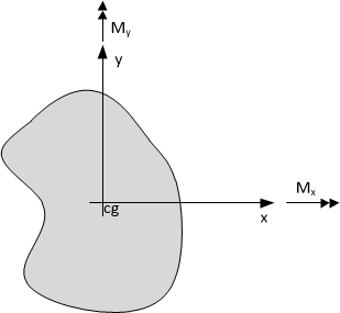
The figure below shows an arbitrary asymmetric section with moments Mx and My about the x and y axes.

Let fx and fy be the curvatures about the x and y axes, respectively.
Equation 1 relates moments and curvatures.

(Eq. 1)
Solving Equation 1 for curvature gives,

(Eq. 2)
From classical Bernoulli beam theory, curvature is equal to the second derivate of deflection, therefore

(Eq. 3)

(Eq. 4)
Assuming stresses are in the linear elastic range, the principle of superposition is applicable. The following two cases are independent and the summation of the deflection results is the total deflection.
Mx is caused by gravity loads (self-weight of girder) and prestressing that is eccentric with respect to the x-axis. Substituting My = 0 into Equations 3 and 4 yields

(Eq. 5)

(Eq. 6)
The deflections in the x and y directions are found by integrating Equations 5 and 6 two times.

(Eq. 7)

(Eq. 8)
Equation 7 gives the direct vertical deflection.
Re-arranging Equations 7 and 8 gives

(Eq. 9)

(Eq. 10)
Setting Equation 9 equal to Equation 10 and simplifying gives

(Eq. 11)
Equation 11 gives the indirect lateral deflection that results due to the asymmetry of the section.
My is caused by prestressing that is eccentric with respect to the y-axis. Substituing Mx = 0 into Equations 3 and 4 yields

(Eq. 12)

(Eq. 13)
The deflections in the x and y directions are found by integrating Equations 12 and 13 two times.

(Eq. 14)

(Eq. 15)
Equation 15 gives the direct lateral deflection.
Re-arranging Equations 14 and 15 gives

(Eq. 16)

(Eq. 17)
Setting Equation 16 equal to Equation 17 and simplifying gives

(Eq. 18)
Equation 18 gives the indirect vertical deflection that results due to the asymmetry of the section.
Superimposing the deflections from Case 1 and Case 2 gives the total deflection

(Eq. 19)

(Eq. 20)