|
PGSuper
5.0
Precast-prestressed Girder Bridges
|
|
PGSuper
5.0
Precast-prestressed Girder Bridges
|
Longitudinal reinforcement is used in the analysis of several limit state conditions including:
Each of these conditions is described in more detail in the sections below.
Moment Capacity is computing using the strain compatibility method. If longitudinal rebar exists in a section, and the option to use girder longitudinal rebar for moment capacity is enabled, this reinforcement will be utilized when computing the ultimate positive moment capacity only. The effectiveness of partially developed reinforcement will be reduced according to LRFD 5.10.8.2.1 (pre-2017: 5.11.2.1).
NOTE: The value of shear depth, dv, which is used extensively in shear capacity computations, is computed as part of the ultimate moment capacity analysis. Hence, shear capacity can be affected indirectly by the existence of longitudinal reinforcement. We have noted several cases where longitudinal steel reduces dv, which will result in a reduction of vertical shear capacity and may reduce longitudinal reinforcement for shear capacity. This behavior can be quite unexpected.
TIP: The option to use longitudinal reinforcement must be enabled on the Project Criteria - Moment Capacity tab.
Provision 5.7.3.5 (pre-2017: 5.8.3.5) of the AASHTO LRFD Specifications states that, for sections not subject to torsion, longitudinal reinforcement shall be proportioned so that at each section the following equation (5.7.3.5-1) is satisfied:

Where:
As = Area of non-prestressed tension reinforcement
fy = Specified minimum yield strength of reinforcing bars
Aps = Area of prestressing steel on the tension side (half-height) of the member, reduced for any lack of full development
fps = Average stress in prestressing steel at the time for which the nominal resistance of member is required
Mu = Factored moment at the section
dv = Effective shear depth
fm = Resistance factor for moment
Nu = Factored axial force at the section
fa = Resistance factor for axial force
Vu = Factored shear force at section
fv = Resistance factor for shear force
Vs = Shear resistance provided by shear reinforcement
Vp = Shear resistance provided by vertical component of prestressing
q = Angle of inclination of diagonal compressive stresses
Tip: The option to use longitudinal mild steel reinforcement must be enabled on the Project Criteria library - Shear Capacity tab
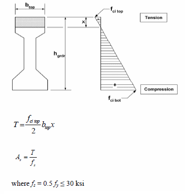
LRFD 5.9.2.3.1b (pre-2017: 5.9.4.1.2), "Temporary Tensile Stress Limits in Prestressed Concrete before Losses, Fully Prestressed Components", allows tensile stress limits for temporary conditions to be increased if sufficient bonded reinforcing bars and/or prestressing steel are provided to resist the tensile force in the concrete computed assuming an uncracked section. The higher allowable limits may be specified for the following cases:
AASHTO suggests that the required tensile steel can be computed per the figure below:

In addition to the basic approach descrbed in LRFD 5.9.2.3.1b (pre-2017: 5.9.4.1.2), the following assumptions are made:
TIP: A common source of confusion is adding reinforcement to your model and finding that the tension limit did not increase. The most common reason for this is that the reinforcement is on the compression side of the beam. Use the stress diagram shown above to compute "x". If your reinforcement is below "x" it is on the compression side and does not contribute to the tensile resistance and therefore does not constitute bonded reinforcement sufficient to resist the tensile force in the concrete computed assuming an uncracked section .