|
PGSuper
3.0
Precast-prestressed Girder Bridges
|
|
PGSuper
3.0
Precast-prestressed Girder Bridges
|
The bridge modeled in the default WF74G template isn't exactly what we need. In the next few sections you will learn how to locate the bridge piers and establish the framing plan for the bridge girders.
We define the bridge beginning with the piers. The piers are where the bridge geometry intersects the roadway geometry (for this example, we'll just go with the default roadway). The locations of the piers establish the location of the bridge along the alignment.
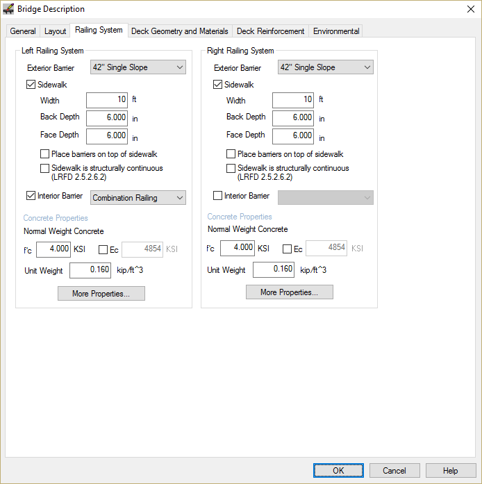
The General Features and Pedestrian Only Bridge tutorials explain step-by-step how to define the basic bridge configuration. These steps won't be repeated here. We will focus only on the bridge railing systems and sidewalks.
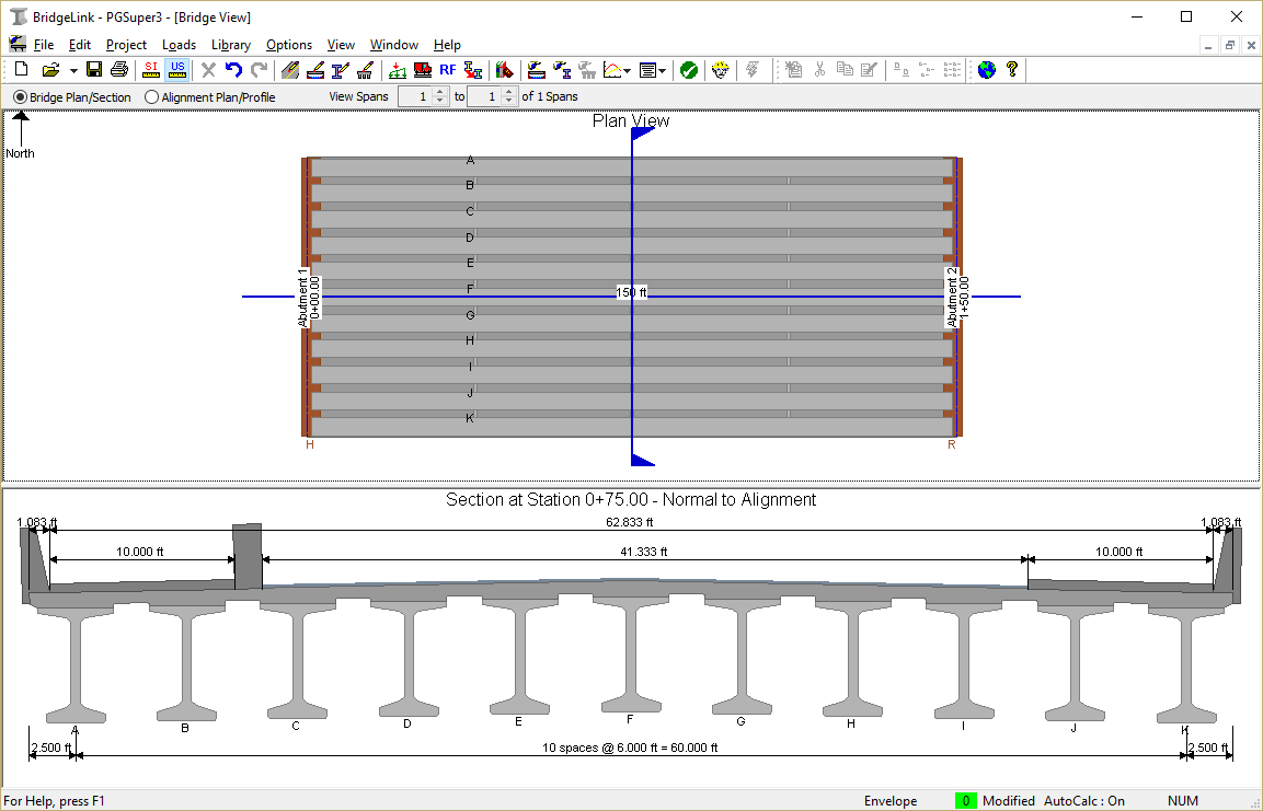
The Bridge Model View is updated to reflect the current project data.
 1.8.11