PGSuper  3.0
Precast-prestressed Girder Bridges
Editing the Bridge Model

The bridge modeled in the W58G template isn't exactly what we need. In the next few sections you will learn how to setup the roadway alignment and profile, locate the bridge piers, and establish the framing plan for the bridge girders.

Roadway Alignment and Profile

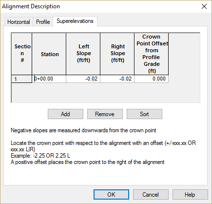
No matter how you slice it, highway bridges are part of the road. Since PGSuper is based on the assumption that you are working with a real bridge, there must be a real roadway that defines the geometry of the structure. We start describing our project by entering information about the roadway alignment.

Describing the Alignment

  1. Select Edit > Alignment.... This will bring up the Alignment Description Window.
  2. Select the Horizontal tab. Enter the information shown below. If the alignment had horizontal curves, they would be described in this dialog. A horizontal control point can be input for coordinate geometry calculations. The default values are sufficient for this example.
    Tutorial_General_Alignment_Horizontal.png
  3. Select the Profile tab. Enter the information shown below. If this project had vertical curves, they would be entered on this tab.
    Tutorial_General_Alignment_Profile.png
  4. Select the Superelevations tab. Enter the information shown.
    Tutorial_General_Alignment_Superelevation.png

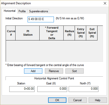
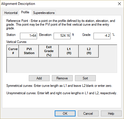
NOTE: The bridge geometry is parametrically linked to the roadway alignment. The bridge geometry will automatically update if the alignment changes.

Bridge Framing

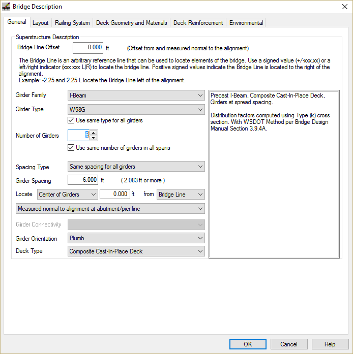
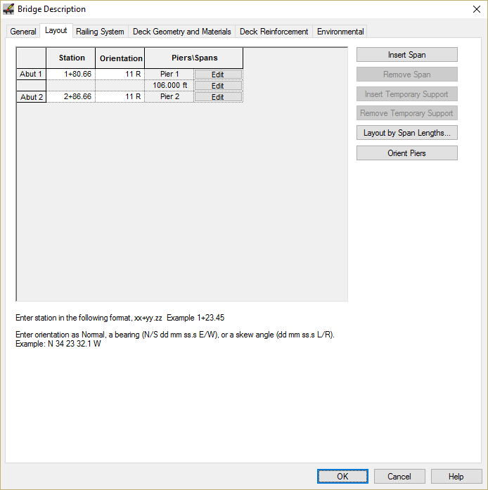
Now that the roadway geometry is defined, we will define the bridge beginning with the piers and abutments. The piers and abutments are where the bridge geometry intersects the roadway geometry. The locations of the piers establish the location of the bridge along the alignment.

Defining the Bridge

  1. Select Edit > Bridge.... This will bring up the Bridge Description window. The general bridge information is described on the General tab. Since our bridge has a very simple configuration, most of the details of the framing can be described on this tab. The project template gets us very close with the bridge configuration. The only change that needs to be made is to set the number of girder lines to 6.
    Tutorial_General_Bridge_Description_General.png
  2. Select the Layout tab. This is were the piers are located and oriented. Enter the information shown below by either entering it directly into the grid.
    Tutorial_General_Bridge_Description_Layout.png
  3. We will use the default Railing System defined in the W58G template. However, if we needed to use a different railing or traffic barrier, define a sidewalk, or add an interior pedestrian barrier, this could be done on the Railing System tab.
  4. Select the Deck Geometry and Materials tab. This is where we will describe the bridge deck. The cross section, material, and wearing surface input are self-explanatory. The Plan (Edge of Deck) input needs a bit more explanation. In PGSuper, the deck width is described by the distance from the Alignment or the Bridge Line to the left and right edges. For constant width decks with edges that parallel the alignment, the left and right deck edge offset only needs to be defined at one location. For our bridge, enter the edge of deck input shown below.
    Tutorial_General_Bridge_Description_Deck.png

This completes the description of the bridge.

Press [OK]. Notice that the Bridge Model View is updated to reflect the current project data. With the exception of the application of user-defined loads, we are done with the input.

NOTE: More complex bridges can be modeled in PGSuper. Different girder cross sections, within the same general type of girder can be assigned to each girder line. The number of girder lines can differ between spans. The girder spacing can also differ between spans and within a span.

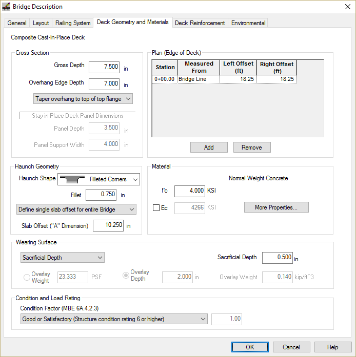
NOTE: Bridge decks with complex geometry can be easily described in PGSuper. By entering the deck edge offset at various stations and the transitions between these offsets, many different types of deck geometry can be modeled. The deck edge can be transitions between the edge points with a Parallel transition (deck edge is parallel to alignment between points), linear, or a spline curve.