|
PGSplice
4.1
Precast-prestressed Spliced Girder Bridges
|
|
PGSplice
4.1
Precast-prestressed Spliced Girder Bridges
|
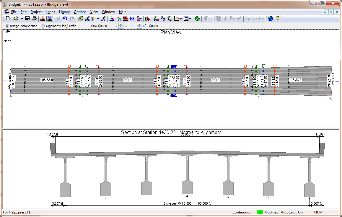
The Bridge View gives a global perspective of your bridge structure. The view is divided into three regions; the Control Bar, the Plan View, and the Elevation View.
The Control Bar is located at the top of the Bridge View. The controls on the Control Bar allow you to select the viewing mode and the extents of the bridge that are displayed.
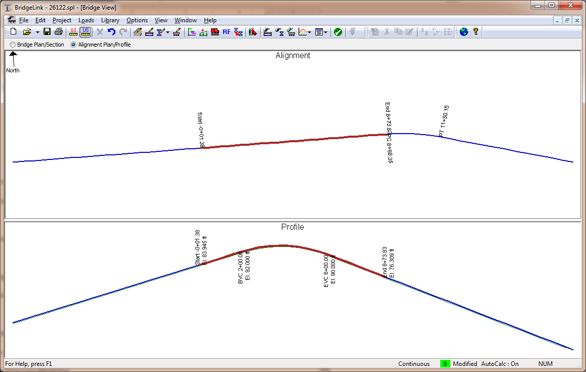
There are two viewing modes for Bridge View; Bridge Plan/Section and Alignment Plan/Profile. These modes show the bridge and alignment models respectively.


The view is divided into two panes. In bridge mode, the upper pane contains the plan view of the structure and the lower pane shows a cross section. The cross section can be taken at any point along the bridge. The horizontal bar between the Plan and Section views may be moved to resize the views. In alignment mode, the upper pane contains the alignment and the lower pane contains the profile. The relative location and size of the bridge is shown on the alignment and profile.
For long bridges, with many spans, it may be difficult to see details when viewing the entire bridge. The span selector is used to set the range of spans to be displayed. Use the up/down arrows to select the range of spans.
The bridge cross section is selected by dragging the section cut tool in the Plan View. A precise section can be specified by double clicking on the section cut tool and entering a station.
When selected, the section cut tool turns red. Select the section cut tool by clicking on it with the mouse. You may use the left and right arrow keys to move the section cut tool one tenth of the span length.
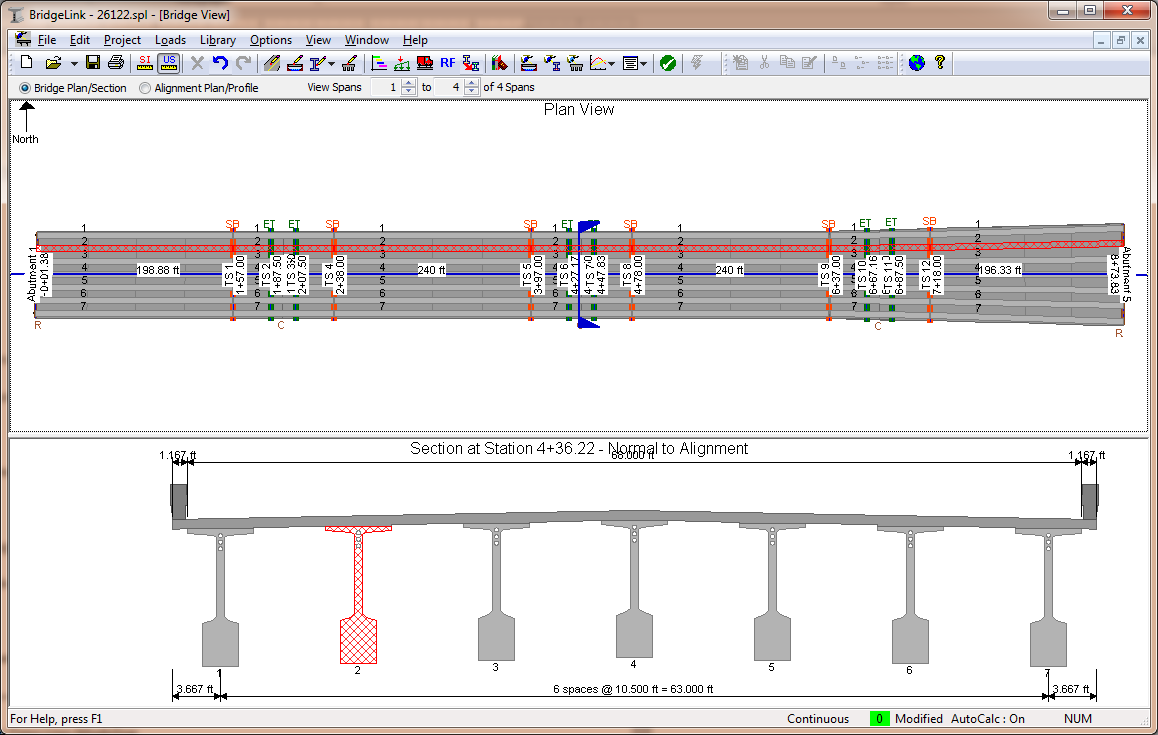
The various bridge components can be selected by clicking on them with the mouse. When selected, the component turns red and is filled with a red hashing. A girder is selected in the figure below.

The spans, piers, girders, deck, alignment, and section cut tool can all be selected.
TIP: You can edit the currently selected item by pressing the Enter key
TIP: You can advance the selection from pier to span to pier using the left and right arrow keys.
TIP: You can advance the selection from girder to girder using the up and down arrow keys
There are several noteworthy elements of the views. These elements provide at a glance information about the bridge model.
| Item | Description |
|---|---|
| North Arrow | The orientation of the bridge is indicated by the North arrow found in the upper left corner of the Plan View. The view can be configured so that North is always up or North is oriented to make the bridge fit best into the view. |
| Tool Tips | When the mouse hovers over many of the view elements such as girders and piers, a tool tip window will be displayed. This tool tip contains detailed information about the element. |
| Boundary Conditions | The boundary conditions are indicated by a small symbol on the right hand side of a pier. For example, the symbol "Ca" indicates that the girders are modeled as continuous after deck placement. |
There are several ways to edit the bridge model from this view. Each pane has context menus for the various items that can be selected. By right clicking on an item, you are presented with a context menu that provides quick access to commands related to that item. For example, by right clicking on a girder you can quickly access the editing window or create a report.
TIP: Right-clicking in the whitespace betweel selectable items will activate a context menu for the view.
The Bridge View can be customized by enabling and disabling the various properties. To customize the view select View > View Settings > Bridge View.