|
PGS Library Editor
3.0
Master Library File Editor for PGSuper/PGSplice
|
|
PGS Library Editor
3.0
Master Library File Editor for PGSuper/PGSplice
|
Moment capacity is computed using a non-linear strain-compatibility methodology. Non-linear material models are used for concrete materials and reinforcing strands.
A non linear approach is used in lieu of the AASHTO or PCI approaches because the research done in Reference 1 (below) has shown that for T-beams with different concrete strengths in the flange and web, the traditional equivalent rectangular concrete compressive stress distribution does not provide a reliable estimate of flexural strength.
The basic theory and assumptions for the non-linear analysis are:
NOTE: The maximum allowable prestressing requirements are still checked for this method per LRFD 5.7.3.3.1. Sections that do not pass this criteria will fail the moment capacity specification check.
The non-linear compressive behavior of prestressed beam sections is modelled by slicing the compression area of the section into horizontal strips. Strains are computed at the midpoint of each strip and then stresses are computed using the concrete material model. The moment contribution by each strip is then determined by multiplying the stress in the strip by the strip area to get the force and then multiplying this force by the distance from the strip's geometrical centroid to the neutral axis. First 30 strips are used. If the program cannot converge on a solution, then 50 and 100 strips are used. The strips are re-generated each time the neutral axis location is changed.
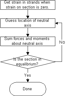
Ultimate moment capacity is computed relative to the condition of zero strain in the non-prestressed materials in the cross section. The following flow chart illustrates the high level procedure for this method:

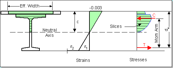
The figure below shows the equilibrium state from which the nominal moment capacity is obtained:

The strain e2 is the strain in the prestressing steel at the effective level of prestress. The strain e1 is the strain associated with the flexure of the cross section. The resultant compressive force, C, acts at the centroid of the compression region. The tensile force T, acts at the location of the resultant of the strand forces.
NOTE: de is the "effective depth from the extreme compression fiber to the centroid of the tensile force in the tensile reinforcement". Strands that are further away from the extreme compression fibers are strained more that those strands that are closer. This results in the centroid of the resultant tensile force being lower in the cross section than the geometric centroid of the prestressing strands..
The cross sectional geometry used for calculating the moment capacity of a girder is the same as that used for calculating section properties. Mild steel longitudinal reinforcement in the girder and in the deck is not considered in the capacity calculation.
The initial strain in the prestressing steel, e2, is computed as fpe/Eps.
As mentioned above, the stress/strain material model for the prestressing steel is computed using the "power method" where eps = e1 + e2. The equation, and a graph, for grade 270 steel are given below.

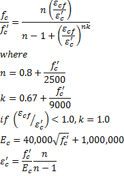
The stress in the concrete, f'c, is determined from the formulas shown below (see Reference 2):

NOTE: The information in this section is only applicable to PGSuper projects with the Design Criteria based on the AASHTO LRFD Bridge Design Specifications, 3rd Edition with 2005 interim provisions and earlier.
The maximum amount of reinforcement is limited such that c/de <= 0.42. When this ratio is exceeded, the maximum design moment capacity is computed in accordance with LRFD C5.7.3.3.1.
There is a sudden drop in usable capacity when c/de transitions from just below 0.42 to just over 0.42. Furthermore, the equations in LRFD C5.7.3.3.1 do not adequately account for the different concrete materials in the deck and girder. WSDOT uses a variable capacity reduction factor method for dealing with this situation.
If the design criteria in this program is set to use the WSDOT BDM method of computing the capacity of over-reinforced sections, the nominal capacity will be computed using the strain compatibility analysis as described above. Then a reduced capacity reduction factor will be computed by