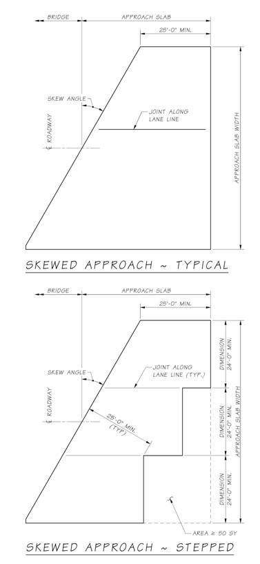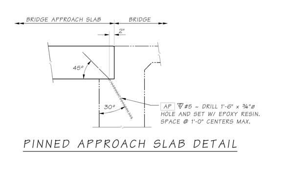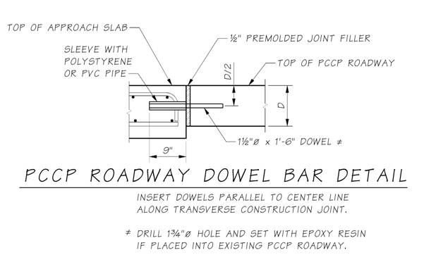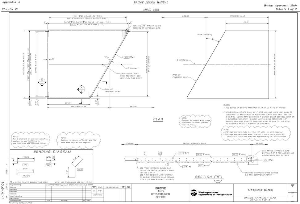
Plan View Reinforcement needs only to be shown by size, spacing, and edge clearance. The number and total spacing can be determined by the contractor. Be sure to include the traffic barrier bars and additional traffic barrier reinforcement in the plan view if applicable. Also remember that the spacing of the AS1 bars decreases near joints. Bar List Retrofit Details The pinning option is only allowed as an approach slab addition or retrofit to an existing bridge. Figure 10.6.6-1 shows the pinning detail. As this detail eliminated the joint between the approach slab and the bridge, the maximum bridge superstructure length is limited to 150 feet. The Bridge Design Engineer may modify this requirement on a case by case basis. Additionally, if the approach slab is adjacent to PCCP roadway, then the detail shown in Figure 10.6.6-2 applies. PCCP does not allow for as much movement as HMA and a joint is required to reduce the possibility of buckling. All approach slabs will have a similar detail. Staging plans will most likely be required when adding or retrofitting approach slabs on existing bridges. The staging plans will be a part of the bridge plans and should be on their own sheet. Coordination with the region is required to ensure agreement between the bridge staging sheet and the region traffic control sheet. The longitudinal construction joints required for staging shall be located on lane lines. As there may not be enough room to allow for a lap splice on the bottom transverse bars, a mechanical splice option should be added.
Approach slabs are bid on a square yard quantity. All the information in the former barlist was becoming confusing, and is not needed. The only information required, and that is contractual, is the bending diagram. As far as retrofit goes, widening the pavement seat and adding approach anchors was the only option until recently. Getting all of the approach anchors aligned properly, especially on a skewed bridge, is not an easy task. If the anchors are not aligned, then the connection acts more like a pinned connection than an expansion connection. Additionally most pavement seats on older bridges are not long enough to allow for the expansion. The seat had to be widened adding construction time and money. Allowing for a pinned connection would reduce the amount of construction time required and the cost of the project.
cc: Mohammad Sheikhizadeh, Bridge Construction - 47354
Note: For a PDF of Figure 10.6.4-1, click here.
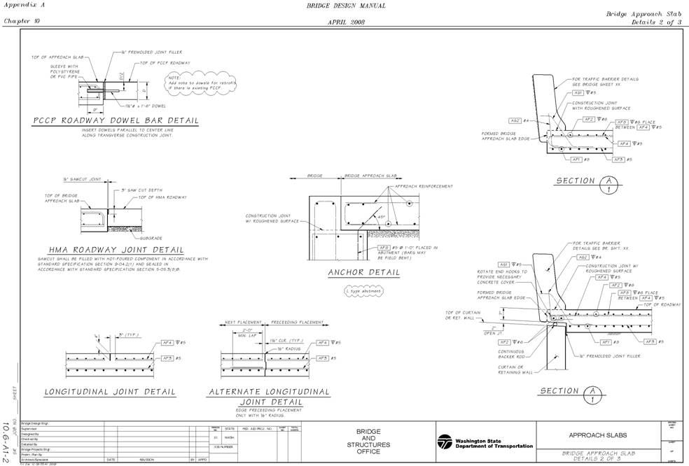
Note: For a PDF of this sheet, click here.
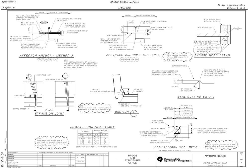
Note: For a PDF of this sheet, click here.
Note: For a PDF of this sheet, click here.
|