Design Memorandum


TO:                  All Design Section Staff

FROM:            Bijan Khaleghi
DATE:             August 20, 2009
SUBJECT:       Confinement Reinforcement for Columns and Shafts


This memo is intended to clarify office policy regarding confinement reinforcing for columns and shafts:

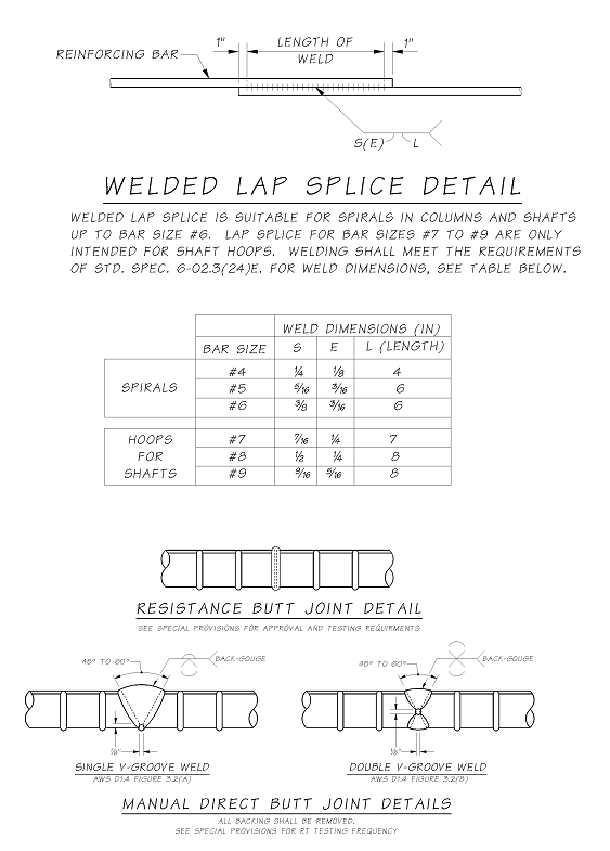
  • Spirals are the preferred confinement reinforcing for columns. Details shall be as shown in the BDM. Welded laps are used for splicing and terminating spirals, BDM fig. 7.4.5-3. The single sided weld has been used exclusively in construction and is preferred. The double sided weld detail should be removed in future plans. Avoid bundled spirals where both bars are required to terminate at the same location (four bars stacked at the lap weld).

  • Where hoops are required for columns, they shall be shop fabricated using either a manual direct butt weld per AWS D1.4 fig. 3.2 (A) or (B), or resistance butt welded. Ultimate couplers, as defined by Caltrans specifications, may be considered provided cover and clearance requirements are accounted for. A list of potential couplers is shown below. Some ultimate couplers are currently listed on the QPL.

  • Shaft lateral reinforcing shall be sized to accommodate 6” minimum spacing, or as noted in BDM 7.8.2. Spirals are preferred if the 6” spacing is achievable with #6 spiral or smaller. Otherwise, hoops of sizes #7 through #9 may be used. Welded lap splices for shaft hoops shown in the BDM, Figure 7.8.2-1, are allowed as long as the shaft is capacity protected against forming a plastic hinge. The single sided weld is preferred. Resistance welded hoops may be used at the contractor’s option. Hoops for shafts shall be shop fabricated or field welded before installation in the shaft cage. A number of ultimate couplers are suitable for field installation with the shaft cage.

  • Only manual welded splices and mechanical couplers are covered by the Standard Specifications. Welded direct butt joints shall be tested by radiographic examination (RT) at a testing frequency of 25%. This requirement is not currently covered by the Standard Specification.

  • Where hoops or ultimate couplers are used, the plans should show a staggered splice placement pattern. Where interlocking hoops are used, the splices should be located in the column interior.


Potential List of Ultimate Couplers for Hoops:

Headed Reinforcement Corp. (HRC)              Xtender Series 500 Coupler 1

BarSplice                                                               BPI-GRIP XL 2

Dextra                                                                    Bartec Position Splice 3

Dayton Superior                                                  D-107 US/MC-SAE Position Coupler 3

Erico                                                                       Lenton Plus Position Coupler 3

HRC                                                                       490 Position Coupler 3

Dayton Superior                                                  Bar-Lock L 3

1 This coupler works without threading the rebar.  It is relatively short compared to other couplers.   Both shop and field installation is possible.   This is not currently on the QPL. 

2 Portable presses are available for field swaging. 

3 Some threaded or long couplers may not be practical except for very large diameter hoops.  Threading ends of formed hoops may be difficult or not fit proprietary threading machines.  Threading bars prior to forming hoops is acceptable if threads are not subsequently damaged.  All threaded couplers require the position type for hoops.


Background:

Reference to preferred confinement method (spirals) can be found in the latest edition AASHTO Guide Specifications for LRFD Seismic Bridge Design C8.6.3. There is considerable construction history using spirals.

Additionally, the requirement for spiral or butt-welded hoops for plastic hinge regions, where displacement ductility is greater than 4 can be found in section 8.8.7.

The long standing practice of using welded lap splices for spirals is currently acceptable under the Structural Welding Code – Reinforcing Steel AWS D1.4 up to bar size #6. Testing was recently performed at the materials laboratory in Tumwater for bar sizes up to #9. All tests achieved full tensile capacity (including 125% of yield strength). These results substantiate the use of welded lap splices for hoops up to bar size #9, provided they are not located in plastic hinge regions. Until welded lap splices for hoops are allowed by the seismic design code in plastic hinge regions, they should not be used in such fashion. Do not use #10 or larger lap welded hoops without further testing.

Resistance butt-welded hoops are currently available from Caltrans approved fabricators in California. The cost should be comparable to the welded lap splice, so it may prove to be an economical substitution to the welded lap splice. The manual direct butt weld per AWS D1.4 fig. 3.2, including radiographic examination, is cost prohibitive for large quantities. Ultimate couplers should have a cost advantage over manual direct welds plus testing, and also allow current cage construction practices.

There is an ongoing study for fabricating fixed hoop reinforcing cages. Information from this study will be forthcoming.


If you have any questions regarding these issues, please contact Nate Brown at 705-7219, or Bijan Khaleghi at 705-7181.

cc:   Mohammad Sheikhizadeh, Bridge Construction - 47354

       F. Posner, Bridge and Structures – 47340


Note:  For a PDF of this design memo, click here.