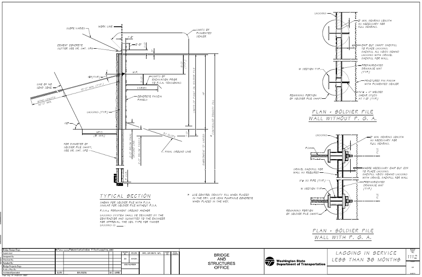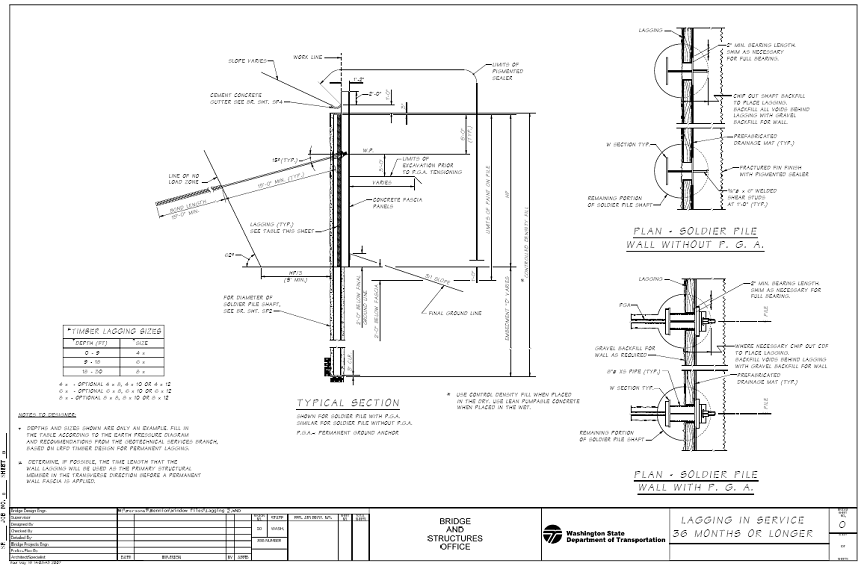
The Geotechnical Services Branch will specify when lagging shall be designed for an additional 250 psf surcharge due to temporary construction load (and which shall also be shown in the Plans). The lateral pressure transferred from a moment slab shall be considered in the design of soldier pile walls and lagging. The expected life cycle of timber lagging is considered to be less than the service life of the structure, namely 75 years for all structures designed in accordance with LRFD Design Specifications. This limited service life of the lagging shall be considered when timber lagging is specified. Therefore timber lagging shall be used only if less than 75 years of service life is acceptable for the specific project. This could be the case if the wall is due to be modified in the future due to widening, or if a permanent fascia is to be constructed to carry the load at some point in the future. Hem-fir wood species, due to the inadequate durability in wet condition, shall not be used for timber lagging. Temporary Timber Lagging
(1) Soil Type is defined in WAC 296-155 Safety Standards for Construction Work, Part N (Excavation, Trenching, and Shoring).
Permanent lagging may be used with precast fascia panels. In this application, permanent is intended to last the design life cycle (75 years) of the wall. Timber lagging does not have this life cycle capacity, but can be used when both of the following conditions exist:
Precast concrete fascia panels shall be designed to carry 100% of the load that could occur during the life of the wall. When timber lagging (including pressure treated lumber) is designed to be placed behind a precast element, conventional design practice is to assume that lagging will eventually fail and the load will be transferred to the precast panel. If another type of permanent lagging is used behind the precast fascia panel, then the design of the fascia panel will be controlled by internal and external forces other than lateral pressures from the soil (weight, temperature, Seismic, Wind, etc.). The connections for precast panels to soldier piles shall be designed for all applicable loads and the designer should consider rigidity, longevity (to cyclic loading, corrosion, etc.), and load transfer.
Traditionally, lagging acts as a temporary structural member that transfer loads to the soldier piles so that a fascia can be placed on the front of the wall. "Temporary" is not a condition that the LRFD code addresses very thoroughly, but the timeframe is generally considered to be 36 months of service. Previous design methodology was to use a 50% reduction on the loads applied to the soldier piles, so as to account for soil arching effects. Industry practices have shown that the loads applied to temporary lagging, and soldier pile shoring walls, can not be related to the loads that the soldier piles see. FHWA, in 1975, produced a document that discusses this issue and provided a table that gives recommended thicknesses for timber lagging based on soil materials and soldier pile spacing. The mechanics of soil arching has shown that depth does not have a significant impact on loads applied to lagging elements, as it does to the soldier piles themselves. Lagging elements tend to be more flexible and deflect under the loads applied, thereby engaging the soil arching effects of the soils to transfer these loads into the soldier piles. The FHWA table was generated based on decades of experience and by meeting deflection requirements less than 1 inch. In order to use this table and equivalent moments, the contractor shall be required to monitor deflections in the lagging. The post-construction deflections (once material has been compacted behind the walls) shall not exceed S/240, where S is the effective lagging span between soldier piles, defined as edge of flange to edge of flange plus ˝ the bearing area of the lagging on each side (2” minimum bearing area). This information and table will be included in Section 6-16.3(6) of the Standard Specifications. Temporary lagging will be treated like any other shoring design and left to the responsibility of the contractor to apply whatever material is appropriate and available. Permanent lagging will be the responsibility of the engineer and shall be timber lagging unless the Geotechnical Services Branch specifies another material.
cc: Mohammad Sheikhizadeh, Bridge Construction Engineer - 47354
|


