
Design Memorandum
TO: All Design Section Staff
FROM: Bijan Khaleghi
DATE: August 12, 2006
SUBJECT: A-Dimension Revisions
The following revisions have been made to “A” Dimension Calculations. These revisions replace the BDM article 5.7.1C as follows:
Appendix 5-B1 shall be replaced in it’s entirety with the following:
Appendix 5-B1: “A” Dimension for Precast Girder Bridges
Introduction
The girder haunch is the distance between the top of a girder and the bottom of the roadway slab. The haunch varies in depth along the length of the girder accommodating the girder camber and geometric effects of the roadway surface including super elevations, vertical curves and horizontal curves.
The basic concept in determining the required “A” dimension is to provide a haunch over the girder such that the top of the girder is less than the fillet depth (typically ¾”) below the bottom of the slab at the center of the span. This provides that the actual girder camber could exceed the calculated value by 1¾” before the top of the girder would interfere with the bottom mat of slab reinforcement.
It is desirable to have points of horizontal and vertical curvature and super elevation transitions off the bridge structure as this greatly simplifies the geometric requirements on the girder haunch. However, as new bridges are squeezed into the existing infrastructure it is becoming more common to have geometric transitions on the bridge structure.
Each geometric effect is considered independently of the others. The total geometric effect is the algebraic sum of each individual effect.
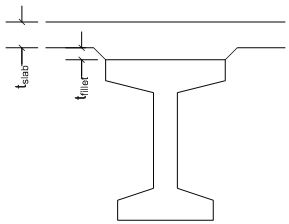
Fillet Effect
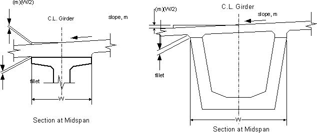
The distance between the top of the girder and the top of the roadway surface, must be at least the thickness of the roadway slab plus the fillet depth.

Excessive Camber Effect
The girder haunch must be thickened to accommodate any camber that remains in the girder after slab casting. This is the difference between the “D” and “C” dimensions from the Girder Schedule Table. Use a value of 2 ½” at the preliminary design stage to determine vertical clearance.

Profile Effect
The profile effect accounts for changes in the roadway profile along the length of the girder. Profile changes include grade changes, vertical curve effects, and offset deviations between the centerline of girder and the alignment caused by flared girders and/or curvature in the alignment.
When all of the girders in a span are parallel and the span is contained entirely within the limits of a vertical and/or horizontal curve, the profile effect is simply the sum of the Vertical Curve Effect and the Horizontal Curve Effect.

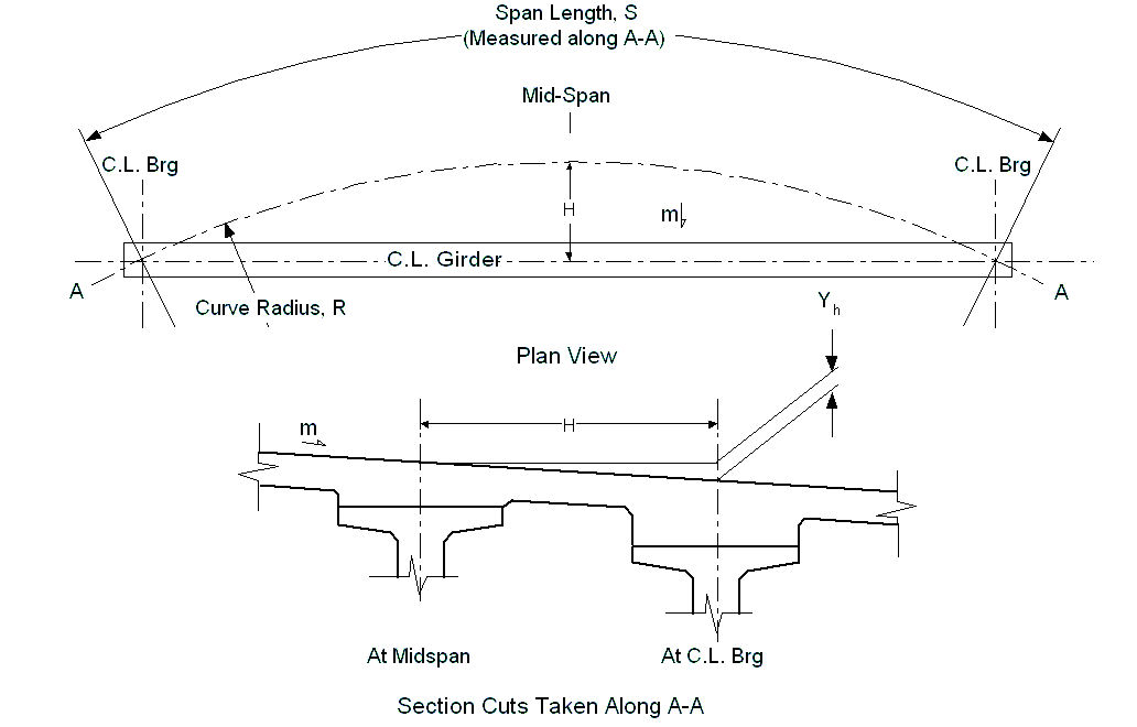
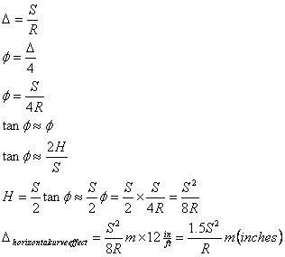
The horizontal curve effect is, assuming a constant super elevation rate along the length of the span,  where S is the length of curve in feet, R is the radius of the curve in feet, and m is the crown slope. The horizontal curve effect is in inches. where S is the length of curve in feet, R is the radius of the curve in feet, and m is the crown slope. The horizontal curve effect is in inches.
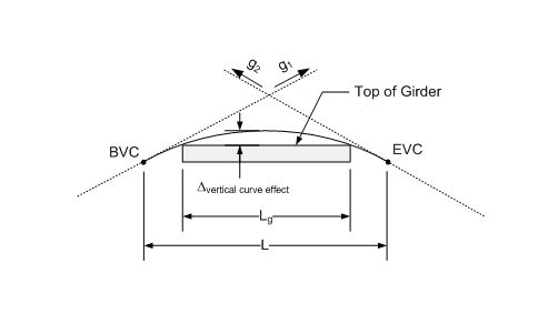
The vertical curve effect is
 where G is the algebraic difference in profile tangent grades (G = g2 - g1) (%), Lg is the girder length (feet), and L is the vertical curve length (feet). The vertical curve effect is in inches and is positive for sag curves and negative for crown curves.

If one or more of the following roadway geometry transitions occur along the span, then a more detailed method of computation is required:
- change in the super elevation rate
-
- grade break
-
- point of horizontal curvature
-
- point of vertical curvature
-
- flared girders
The exact value of the profile effect may be determined by solving a complex optimization problem. However it is much easier and sufficiently accurate to use a numerical approach.
The figure below, while highly exaggerated, illustrates that the profile effect is the distance the girder must be placed below the profile grade so that the girder, ignoring all other geometric effects, just touches the lowest profile point between the bearings.
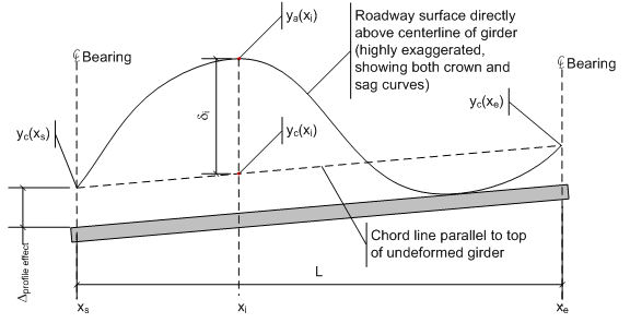
In the case of a crown curve the haunch depth may reduced. In the case of a sag curve the haunch must be thickened at the ends of the girder.
To compute the profile effect:
1. Create a chord line parallel to the top of the girder (ignoring camber) connecting the centerlines of bearing. The equation of this line is-
 -
where
-
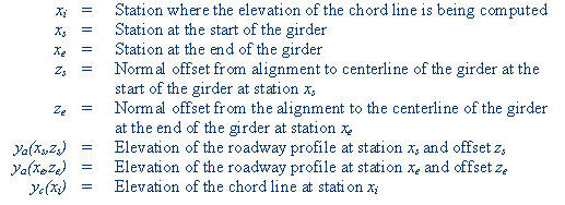
2. At 10th points along the span, compute the elevation of the roadway surface

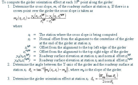
Girder Orintation Effect -
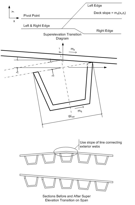
The girder orientation effect accounts for the difference in slope between the roadway surface and the top of the girder. Girders such as I-beams are oriented with their Y axis plumb. Other girders such as U-beam, box beam, and slabs are oriented with their Y axis normal to the roadway surface. The orientation of the girder with respect to the roadway surface, and changes in the roadway surface along the length of the girder (super elevation transitions) define the Girder Orientation Effect.
If the super elevation rate is constant over the entire length of the span and the Y-axis of the girder is plumb, the girder orientation effect simplifies to the Top Width Effect, -

If there is a change in super elevation rate and/or the Y-axis of the girder is not plumb, then once again a more complex computation is required.
"A" Dimension -
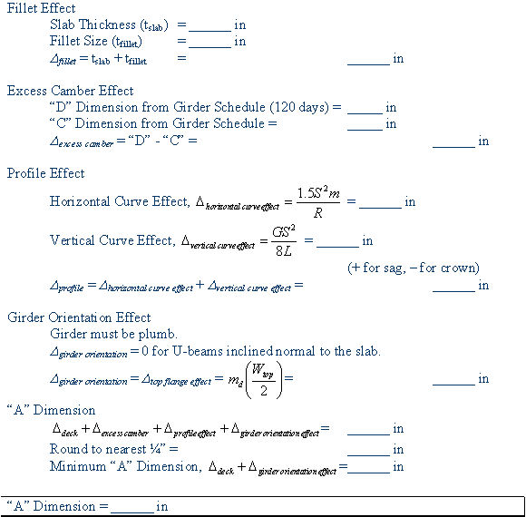
The “A” dimension is the sum of all these effects
-
 -
If a Drain Type 5 crosses the girder, “A” shall not be less than 9 inches
Limitations -
These computations are for a single girder line. The required haunch should be determined for each girder line in the structure. Use the greatest “A” dimension.
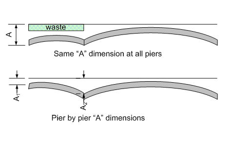
These computations are also limited to a single span. A different haunch may be needed for each span or each pier. For example, if there is a long span adjacent to a short span, the long span may have considerably more camber and will require a larger haunch. There is no need to have the shorter spans carry all the extra concrete needed to match the longer span haunch requirements. With the WF series girders, the volume of concrete in the haunches can add up quickly. The shorter span could have a different haunch at each end as illustrated below.
Stirrup Length and Precast Deck Leveling Bolt Considerations -
For bridges on crown vertical curves, the haunch depth can become excessive to the point where the girder and diaphragm stirrups are too short to bend into the proper position. Similarly the length of leveling bolts in precast deck panels may need adjustment.
Stirrup lengths are described as a function of “A” on the standard girder sheets. For example, the G1 and G2 bars of a WF74G girder are 6’-5”+ “A” in length. For this reason, the stirrups are always long enough at the ends of the girders. Problems occur when the haunch depth increases along the length of the girder to accommodate crown vertical curves and super elevation transitions.
If the haunch depth along the girder exceeds “A” by more than 2 inches, an adjustment must be made. The haunch depth at any section can be compute -

"A" Dimension Worksheet - Simple Alignment
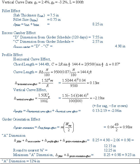
Example -
Slab: Thickness = 7.5”, Fillet = 0.75”
-
WF74G Girder: Wtop = 49”
-
Span Length = 144.4 ft
-
Crown Slope = 0.04ft/ft
-
Camber: D = 7.55”, C = 2.57”
-
Horizontal Curve Radius = 9500ft through centerline of bridge
-
Background:
The revised "A" dimension proposal is more suitable for the BDM and PGSuper Program. This method is completely general and should handle every prestressed girder including trapezoidal tub-girder bridge configuration. The simple method we have always used is incorporated into the text.
If you have any questions regarding these issues, please contact Rick Brice at 705-7174 or Bijan Khaleghi at 705-7181.
cc: Mohammad Sheikhizadeh, Bridge Construction - 47354 -
F. Posner, Bridge and Structures – 47340
|


