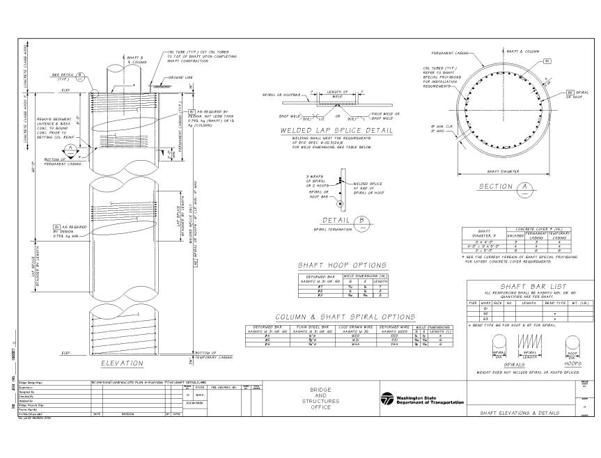
May 14, 2004 This design memorandum summarizes the latest WSDOT-ADSC recommendations on design, detailing, construction of drilled shafts in wet or dry conditions, and cast-in-place concrete pile detailing. This Design Memorandum supersedes Design Memorandum dated March 19,1999. Transverse Reinforcement: Longitudinal Reinforcement: Shaft Concrete: Typical shaft reinforcement and casing details are shown on the attached drawing. The details may vary, depending on the soil conditions and specific design and construction methods and equipment that apply. Pile Detailing: To be consistent with information given for shafts, pile bar lists shall be included in the pile sheets. This list will include the bar’s mark, size, number, length, bend type and total weight. These quantities shall be calculated based on estimated pile tip elevations. A note stating that the quantities are based on estimated pile tip elevations shall be added to the pile bar list. Background: The top of the shaft in typical WSDOT column-to-shaft connection, due to larger shaft diameter, remains in elastic conditions under seismic loads. Therefore, the AASHTO LRFD requirements for confinement of plastic hinging zones become irrelevant. The minimum drilled shaft transverse reinforcing shall not be less than that required for the forces resulting from an elastic analysis nor that required to develop the plastic capacity (1.3Mn=Mp) of the column above, whichever is less. The column-shaft splice zone shall meet the requirements outlined in the TRAC Report titled "NONCONTACT LAP SPLICES IN BRIDGE COLUMN-SHAFT CONNECTIONS". Longitudinal reinforcing in drilled shaft should be straight with no hooks. To facilitate concrete placement and removal of casing, hooks in vertical shaft reinforcing should be avoided. If hooks are necessary to develop moment at the top of a drilled shaft, the hooks should be turned toward the center of the shaft while leaving enough opening to allow concrete placement with a tremie. Shaft longitudinal reinforcing is designed for the plastic moment (1.3Mn) induced by the column or the elastic seismic moment (R=1), whichever is less. This applies to all seismic zones in Washington State. If you have any questions regarding these issues, please contact Patrick Clarke at 705-7220 or Bijan Khaleghi at 705-7181. JK:dsb cc: J. A. Weigel, Bridge and Structures - 47340
|